
Press Enter to move to the next occurrence.

Revision history #
| Version | Date | Editor | Change Description |
| 1.0 | 08.2026 | OD | Initial version |
Introduction #
This document presents the Task Catalogue of the UNUM Truck telematics service (hereinafter referred to as the Task Catalogue), developed by Technoton.
The Task Catalogue is intended for specialists involved in the implementation, configuration, support, and direct operation of the UNUM Truck telematics service.
The Task Catalogue is a reference guide for selecting functionality, configuring, and adapting the UNUM Truck service to the specific operating conditions of monitored Assets:
- Trucks – tractor units, refrigerated trucks, flatbed trucks.
- Special-purpose vehicles – dump trucks, refuse collection vehicles.
- Fuel tankers – tanker trucks, tank semi-trailers, refuellers.
 |
RECOMMENDATION: Before using the Task Catalogue we strongly recommend reviewing the documentation available in the UNUM Guide Center. |
Distinctive features of Tasks:
- Tariff system — Tasks are provided as paid telematics services with daily billing.
- Individual subscription — the required Task is activated strictly for a specifically selected Asset / Group / Geofence.
- Classification by data volume — the Task Class determines the number of monitored Parameters and allows the required information depth to be selected optimally.
- Preconfigured data set — each Task contains a predefined set of Keys in accordance with its functional purpose.
- Ready-to-use monitoring and analysis tools — the corresponding Dashboard Templates and Report Templates are provided with the Task.
- Industry specialization — Tasks are configured with consideration for the equipment type, monitored process, and operating conditions.
- Configuration flexibility — free combination of any Tasks, adaptation to different Asset configurations, and the required number of monitored Parameters.
- Versatility — Tasks can be used for different equipment types, engine models, and control units from different manufacturers.
- Replicability — standard Tasks can be applied repeatedly to similar Assets without redeveloping the functionality.
- Extensibility — as new requirements arise, additional Tasks can be activated, Keys can be added, and the functionality of the Industry Solution can be expanded.
|
WARNING: Technoton reserves the right to make changes to the Tasks presented in this catalogue without prior agreement with customers, provided that the quality and functionality of the UNUM Truck service are maintained. |
1 Tasks for individual Assets #
1.1 Axle Load Monitoring #
Class: 25.
Purpose:
Axle Load Monitoring — provides monitoring of axle load and total Vehicle cargo weight using pressure sensors for air suspension and displacement sensors for leaf-spring suspension. The Task enables monitoring of load on each axle, detection of Vehicle overload, loading and unloading Events, and tracking of suspension Parameters and the diagnostic status of axle load sensors to ensure safe operation.
Required Onboard Equipment:
- telematics gateway CANUp 27 Pro (model code 30) – 1 pc.;
- axle load sensors GNOM DP CAN / GNOM DP S7 / GNOM DDE S7 – 2 pcs.
Industries:
- Fuel & chemicals tankers (code RDF);
- Mining (code MIN).
Role: Operator (code OPR).
Total number of Keys: 25
Occupied Keys: 18 (see Table 1).
Available Keys: 7
Table 1 — Occupied Keys for the Axle Load Monitoring Task
| Source network address |
SPN and specifier (if available) |
Unit of measurement |
Explanation |
| 82 | 582 Axle load | kg | Current Vehicle axle load. |
| 82* | 5347 Lateral Acceleration Extended Range | m/s² | Current lateral acceleration according to sensor data. |
| 83* | 5347 Lateral Acceleration Extended Range | m/s² | Current lateral acceleration according to sensor data. |
| 82* | 5348 Longitudinal Acceleration Extended Range | m/s² | Current longitudinal acceleration according to sensor data. |
| 83* | 5348 Longitudinal Acceleration Extended Range | m/s² | Current longitudinal acceleration according to sensor data. |
| 82* | 5349 Vertical Acceleration Extended Range | m/s² | Current vertical acceleration according to sensor data. |
| 83* | 5349 Vertical Acceleration Extended Range | m/s² | Current vertical acceleration according to sensor data. |
| 82 | 521036 Overload Counter | pcs. | Counter of registered overload Events. |
| 82 | 521037 Load Counter | pcs. | Counter of registered loading Events. |
| 82 | 521038 Unloading Counter | pcs. | Counter of registered unloading Events. |
| 82 | 521182 Axle Weight Mode | – | Current Vehicle loading mode (Empty / Optimal / Maximal / Overload). |
| 82** | 521469 Angle | degrees | Current sensor lever deviation angle. |
| 82 | 521488 Unit DTCs Mask | – | Bit mask of sensor diagnostic trouble codes. |
| 83 | 521488 Unit DTCs Mask | – | Bit mask of sensor diagnostic trouble codes. |
| 82* | 521511 Suspension Air Pressure | kPa | Current air pressure in the air suspension. |
| 83* | 521511 Suspension Air Pressure | kPa | Current air pressure in the air suspension. |
| 82* | 521513 Suspension Air Temperature | °C | Current air temperature in the air suspension. |
| 83* | 521513 Suspension Air Temperature | °C | Current air temperature in the air suspension. |
| * The Key is applicable only when GNOM DDE S7 pressure sensors are used for air suspension. ** The Key is applicable only when GNOM DP CAN / GNOM DP S7 displacement sensors are used for leaf-spring suspension. |
|||
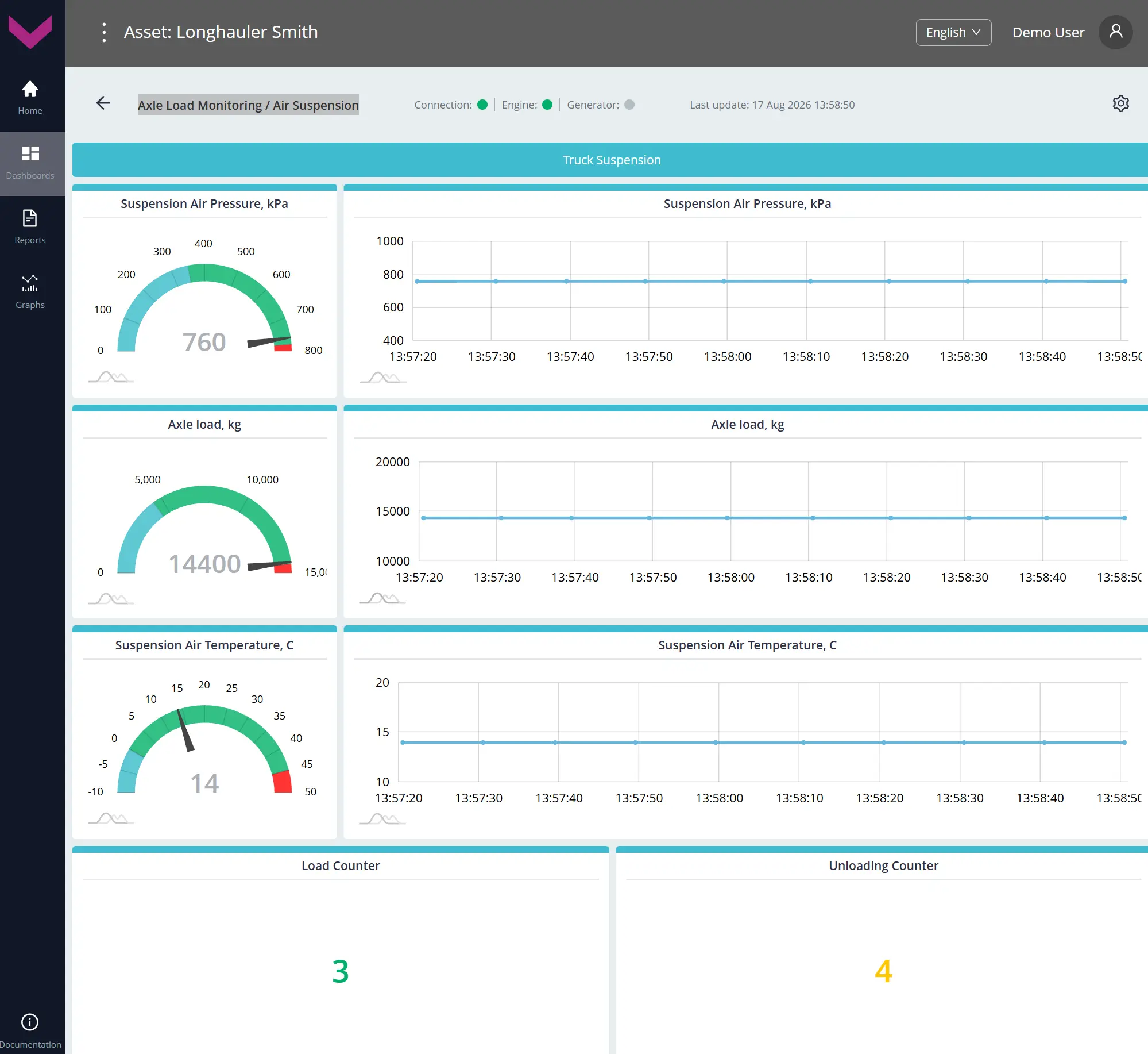
a) real-time data display on the Dashboard *Air Suspension
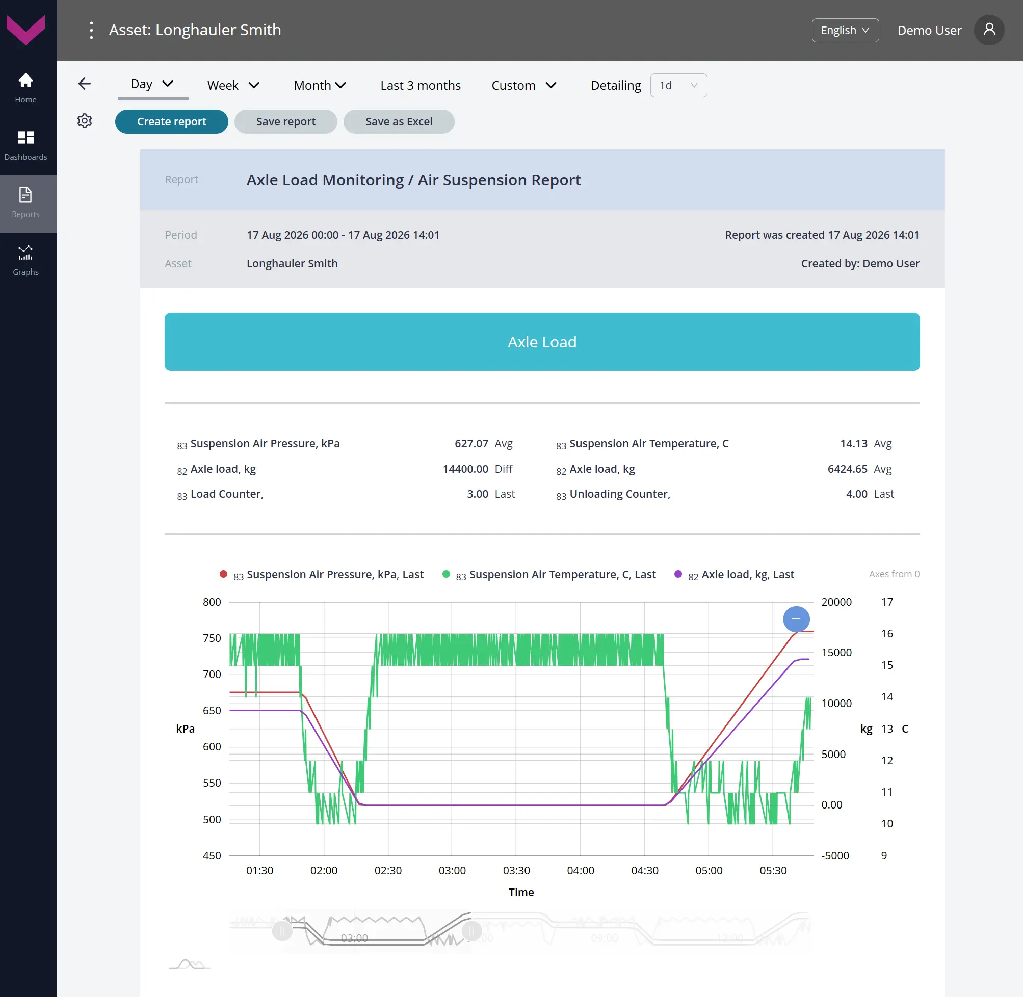
b) Analytical report *Air Suspension Report for a one-day period
Figure 1 — Examples of data display for Task Axle Load Monitoring
1.2 Cargo Tank Monitoring #
Class: 50.
Purpose:
Cargo Tank Monitoring — provides real-time monitoring and analysis over a selected period of fuel level, volume, temperature, and filling status in each compartment of a fuel tanker (up to four compartments in total). The Task enables monitoring of fuel volumes during loading and unloading, tracking of delivery balance, and detection of abnormal fuel level changes and possible discrepancies between actual and expected fuel quantity.
Required Onboard Equipment:
- telematics gateway CANUp 27 Pro (model code 30) – 1 pc.;
- fuel level sensor DUT-E / DUT-E 2Bio / DUT-E S7 / DUT-E 2Bio S7 – 4 pcs.;
- fuel flow meter DFM Marine / DFM Marine S7 – 1 pc.
Industry: Fuel & chemicals tankers (code RDF).
Role: Operator (code OPR).
Total number of Keys: 50
Occupied Keys: 26 (see Table 2).
Available Keys: 24
Table 2 — Occupied Keys for the Cargo Tank Monitoring Task
| Source network address |
SPN and specifier (if available) |
Unit of measurement |
Explanation |
| 111 | 174 Engine Fuel Temp | °C | Current fuel temperature in the flow meter measuring chamber. |
| 101 | 521023 Fuel Tank Level | mm | Current fuel level height in the corresponding cargo tank compartment of the Vehicle. |
| 102 | 521023 Fuel Tank Level | mm | Current fuel level height in the corresponding cargo tank compartment of the Vehicle. |
| 103 | 521023 Fuel Tank Level | mm | Current fuel level height in the corresponding cargo tank compartment of the Vehicle. |
| 104 | 521023 Fuel Tank Level | mm | Current fuel level height in the corresponding cargo tank compartment of the Vehicle. |
| 111 | 521171 Flowmet.Hours Of Operat. | s | Counter of total flow meter operating time over the entire load range. |
| 111 | 521267 Interference sens.count | pcs. | Counter of registered attempts to interfere with the flow meter operation. |
| 111 | 521310 Interference Duration | s | Duration of interference with the flow meter operation when an “Interference” Event is registered. |
| 111 | 521313 Engine fuel rate | l/h | Current hourly fuel consumption according to the flow meter data. |
| 111 | 521314 Total Fuel Used | l | Total fuel consumption counter. |
| 101 | 521457 Temperature | °C | Current fuel temperature in the corresponding cargo tank compartment of the Vehicle. |
| 102 | 521457 Temperature | °C | Current fuel temperature in the corresponding cargo tank compartment of the Vehicle. |
| 103 | 521457 Temperature | °C | Current fuel temperature in the corresponding cargo tank compartment of the Vehicle. |
| 104 | 521457 Temperature | °C | Current fuel temperature in the corresponding cargo tank compartment of the Vehicle. |
| 101 | 521728 Fuel Tank Volume | l | Current fuel volume in the corresponding cargo tank compartment of the Vehicle. |
| 102 | 521728 Fuel Tank Volume | l | Current fuel volume in the corresponding cargo tank compartment of the Vehicle. |
| 103 | 521728 Fuel Tank Volume | l | Current fuel volume in the corresponding cargo tank compartment of the Vehicle. |
| 104 | 521728 Fuel Tank Volume | l | Current fuel volume in the corresponding cargo tank compartment of the Vehicle. |
| 101* | 521773 Third Electrode Frequency | Hz | Current third-electrode measuring generator frequency of the corresponding fuel level sensor. |
| 102* | 521773 Third Electrode Frequency | Hz | Current third-electrode measuring generator frequency of the corresponding fuel level sensor. |
| 103* | 521773 Third Electrode Frequency | Hz | Current third-electrode measuring generator frequency of the corresponding fuel level sensor. |
| 104* | 521773 Third Electrode Frequency | Hz | Current third-electrode measuring generator frequency of the corresponding fuel level sensor. |
| 101* | 521774 Fuel Permittivity Relative | – | Current relative permittivity value of fuel in the corresponding cargo tank compartment, used to identify the fuel type. |
| 102* | 521774 Fuel Permittivity Relative | – | Current relative permittivity value of fuel in the corresponding cargo tank compartment, used to identify the fuel type. |
| 103* | 521774 Fuel Permittivity Relative | – | Current relative permittivity value of fuel in the corresponding cargo tank compartment, used to identify the fuel type. |
| 104* | 521774 Fuel Permittivity Relative | – | Current relative permittivity value of fuel in the corresponding cargo tank compartment, used to identify the fuel type. |
| * The Key is applicable only when using differential fuel level sensors DUT-E 2Bio / DUT-E 2Bio S7. | |||
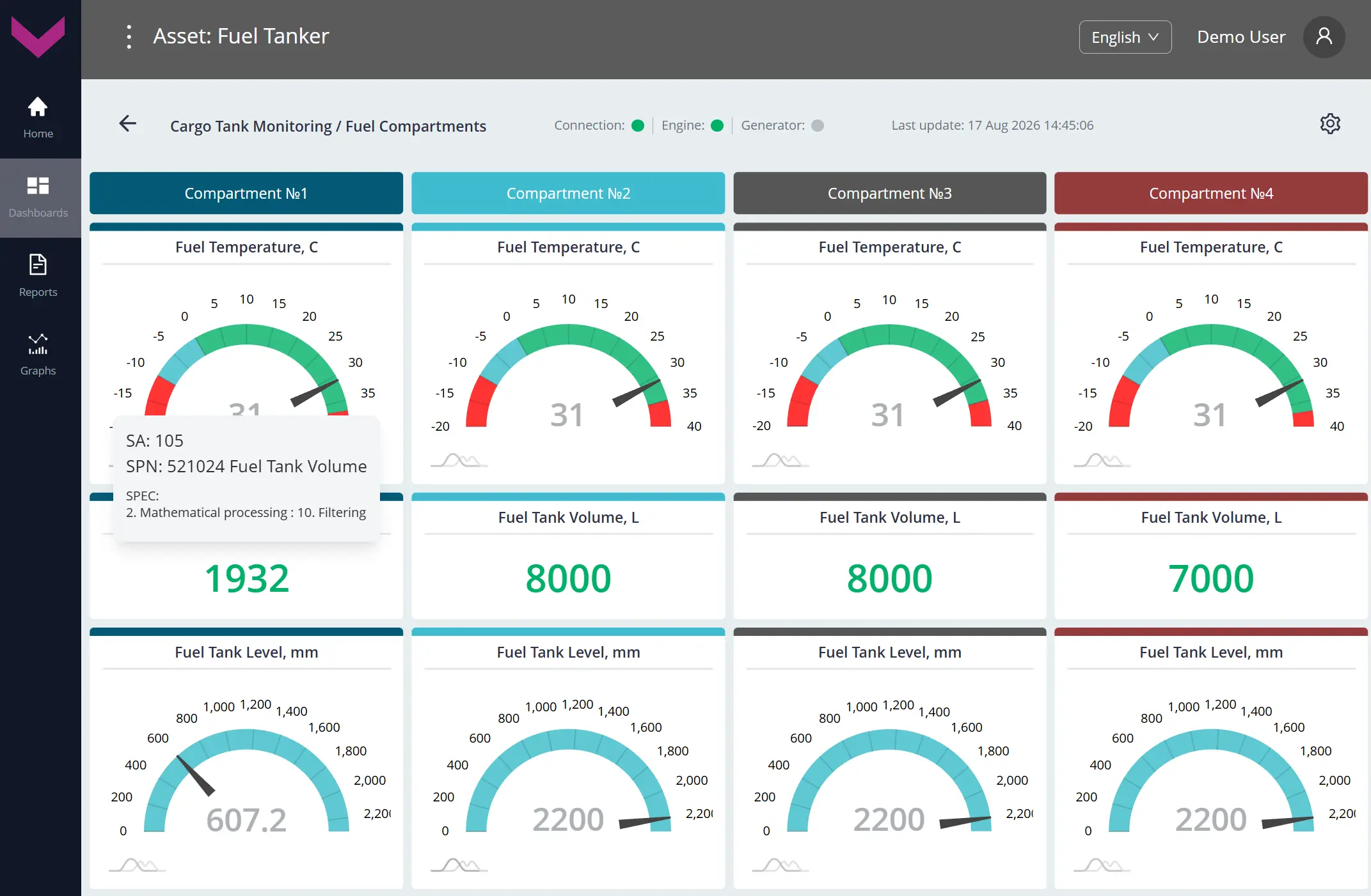
a) real-time data display on the Dashboard *Fuel Compartments
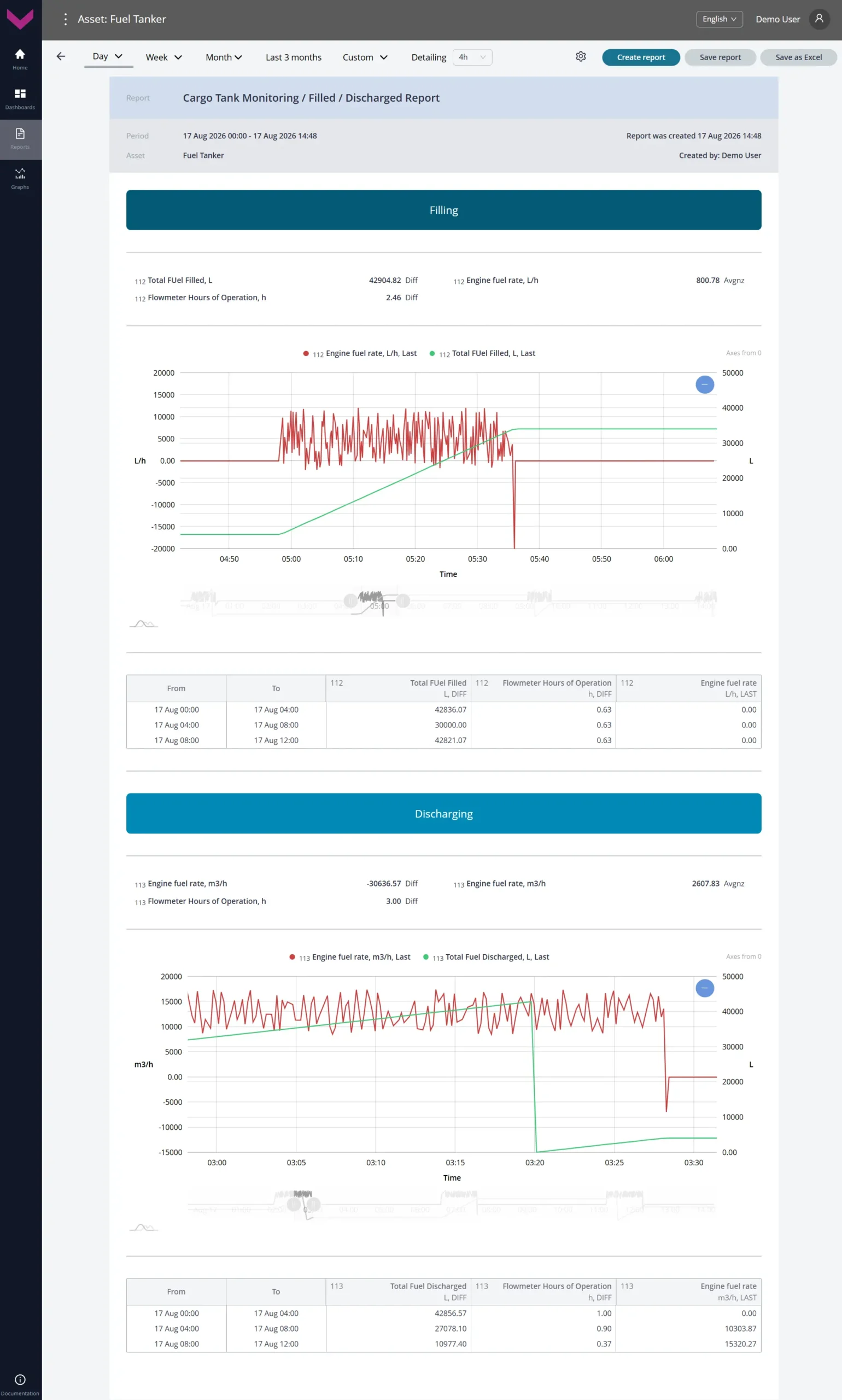
b) Analytical report *Filled / Discharged Report for a one-day period
Figure 2 — Examples of data display for Task Cargo Tank Monitoring
1.3 Fuel Monitoring (RDF) #
Class: 50.
Purpose:
Fuel Monitoring (RDF) — provides real-time monitoring and analysis over a selected period of fuel level, volume, and temperature in the Vehicle fuel tank, as well as engine fuel consumption. The Task enables tracking of refueling and draining Events, monitoring of current and total fuel consumption and fuel consumption per trip, detection of abnormal fuel level changes, and evaluation of Vehicle fuel efficiency and environmental performance.
Required Onboard Equipment:
- telematics gateway CANUp 27 Pro (model code 30) – 1 pc.;
- fuel level sensor DUT-E / DUT-E 2Bio / DUT-E S7 / DUT-E 2Bio S7 – 1 pc.;
- fuel flow meter DFM D / DFM D S7 – 1 pc.
Industry: Fuel & chemicals tankers (code RDF).
Role: Operator (code OPR).
Total number of Keys: 50
Occupied Keys: 28 (see Table 3).
Available Keys: 22
Table 3 — Occupied Keys for the Fuel Monitoring (RDF) Task
| Source network address |
SPN and specifier (if available) |
Unit of measurement |
Explanation |
| 101 | 96 Fuel Level | % | Current fuel level in the Vehicle fuel tank, expressed as a percentage. |
| 101 | 158 On-board voltage | V | Current Vehicle on-board network voltage reported by the fuel level sensor. |
| 111 | 158 On-board voltage | V | Current on-board power supply voltage (from the ignition switch) according to flow meter data. |
| 101 | 174 Engine Fuel Temp | °C | Current fuel temperature in the Vehicle fuel tank. |
| 111 | 174 Engine Fuel Temp | °C | Current fuel temperature in the flow meter measuring chamber. |
| 111 | 183 Engine fuel rate | l/h | Current hourly fuel consumption; for a differential flow meter, differential consumption through both measuring chambers. |
| 111 | 5054 High Res.Total Fuel Used | l | Total engine fuel consumption counter over the entire load range. |
| 111 | 5054 High Res.Total Fuel Used 18. Chamber type : 0. Feed chamber |
l | Counter of the total fuel volume that passed through the feed chamber of the flow meter. |
| 111 | 5054 High Res.Total Fuel Used 18. Chamber type : 1. Reverse chamber |
l | Counter of the total fuel volume that passed through the Reverse chamber of the flow meter. |
| 111 | 5054 High Res.Total Fuel Used 9. Movement mode based on fuel rate : 0. Idle |
l | Total engine fuel consumption in Idle mode. |
| 111 | 5054 High Res.Total Fuel Used 9. Movement mode based on fuel rate : 1. Optimal |
l | Total engine fuel consumption in Optimal mode. |
| 111 | 5054 High Res.Total Fuel Used 9. Movement mode based on fuel rate : 2. Overload |
l | Total engine fuel consumption in Overload mode. |
| 111 | 5054 High Res.Total Fuel Used 9. Movement mode based on fuel rate : 3. Cheating |
l | Total engine fuel consumption in Cheating mode. |
| 111 | 5054 High Res.Total Fuel Used 28. Counter Type : 0. Clearable |
l | Clearable counter of total engine fuel consumption. |
| 101 | 521023 Fuel Tank Level 2. Mathematical processing : 10. Filtering |
mm | Filtered fuel level height in the Vehicle fuel tank. |
| 101 | 521024 Fuel Tank Volume 2. Mathematical processing : 10. Filtering |
l | Filtered fuel volume in the Vehicle fuel tank. |
| 111 | 521171 Flowmet.Hours Of Operat. | s | Counter of total flow meter operating time over the entire load range. |
| 111 | 521171 Flowmet.Hours Of Operat. 9. Movement mode based on fuel rate : 0. Idle |
s | Flow meter operating time counter in Idle mode. |
| 111 | 521171 Flowmet.Hours Of Operat. 9. Movement mode based on fuel rate : 1. Optimal |
s | Flow meter operating time counter in Optimal mode. |
| 111 | 521171 Flowmet.Hours Of Operat. 9. Movement mode based on fuel rate : 2. Overload |
s | Flow meter operating time counter in Overload mode. |
| 111 | 521171 Flowmet.Hours Of Operat. 9. Movement mode based on fuel rate : 3. Cheating |
s | Flow meter operating time counter in Cheating mode. |
| 111 | 521171 Flowmet.Hours Of Operat. 9. Movement mode based on fuel rate : 5. Interference |
s | Flow meter operating time counter in “Interference” mode. |
| 111 | 521171 Flowmet.Hours Of Operat. 28. Counter Type : 0. Clearable |
s | Clearable counter of total flow meter operating time. |
| 111 | 521181 Engn Mode by Fuel Rate | – | Current operating mode of the fuel consumer, determined by the hourly fuel consumption. |
| 101 | 521301 Filled Fuel Volume | l | Fuel volume added to the Vehicle tank during a refueling Event. |
| 101 | 521302 Discharged Fuel Volume | l | Fuel volume drained from the Vehicle tank during a draining Event. |
| 111 | 521864 Total CO2 Emission | kg | Total engine CO₂ emissions automatically calculated from total fuel consumption using the specified CO₂ factor. |
| 111 | 521865 Hourly CO2 Emission | kg/h | Hourly engine CO₂ emissions automatically calculated from hourly fuel consumption using the specified CO₂ factor. |
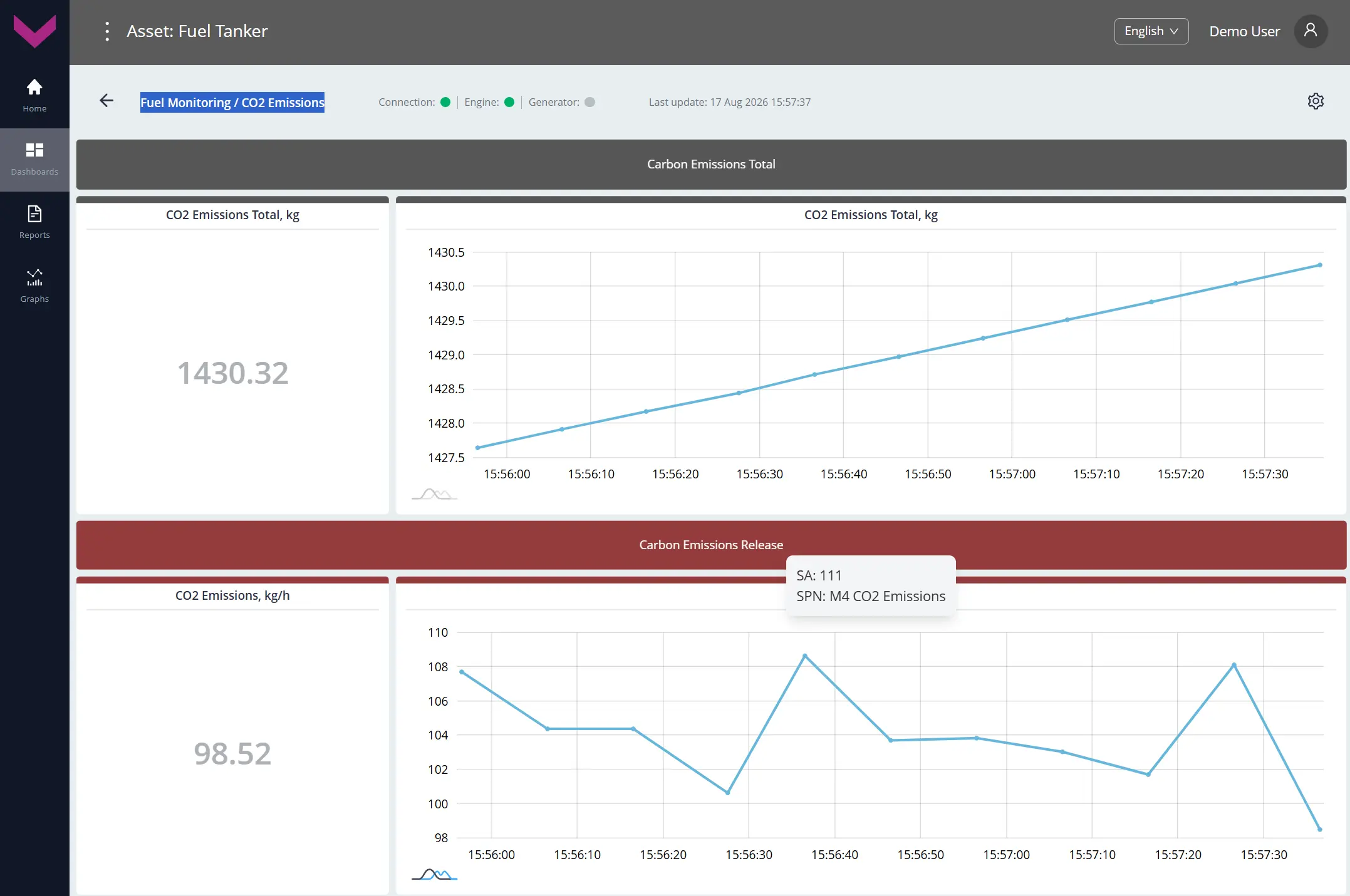
a) real-time data display on the Dashboard *CO2 Emissions
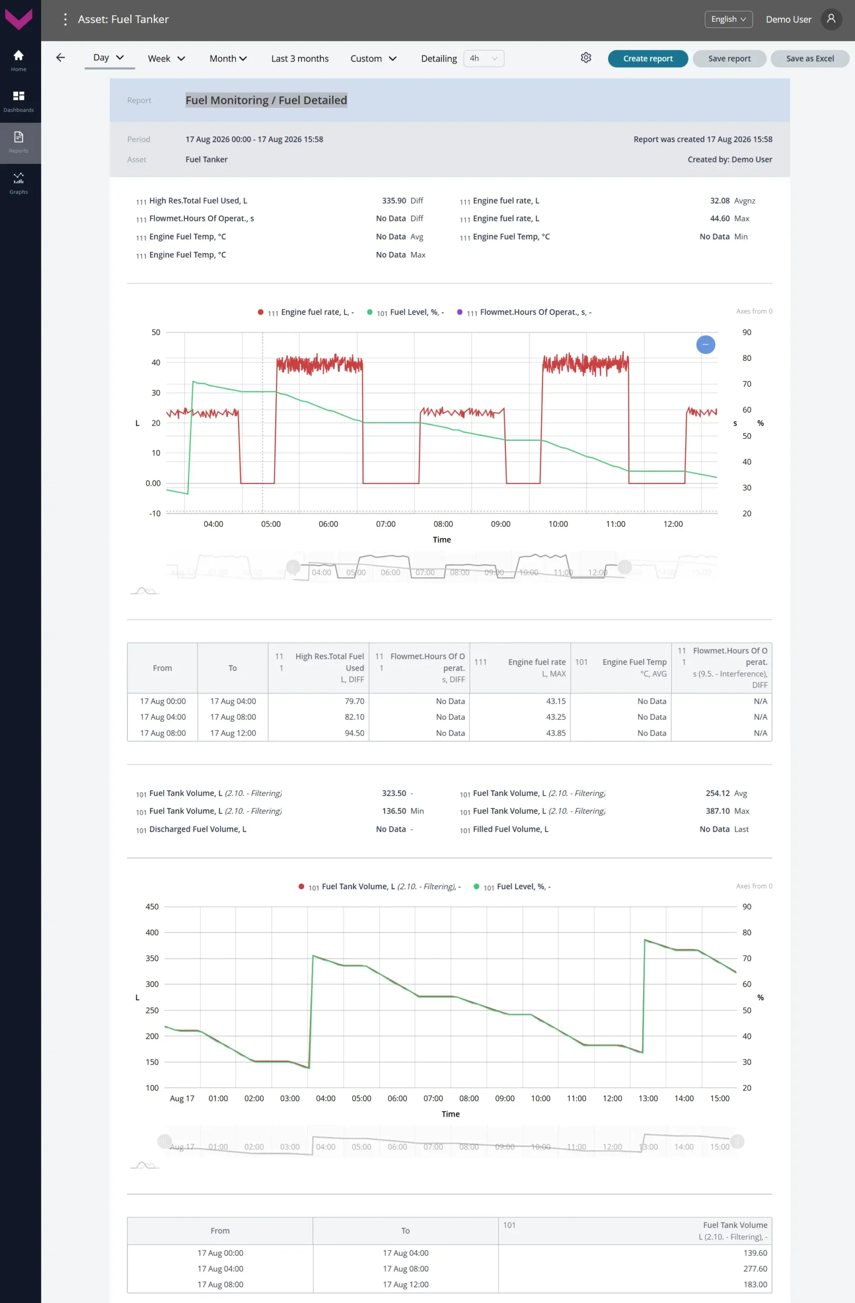
b) Analytical report *Fuel Detailed for a one-day period
Figure 3 — Examples of data display for Task Fuel Monitoring (RDF)
1.4 Fuel Monitoring (MIN) #
Class: 50.
Purpose:
Fuel Monitoring (MIN) — provides real-time monitoring and analysis over a selected period of fuel level, volume, and temperature in the Vehicle fuel tank, as well as engine fuel consumption. The Task enables tracking of refueling and draining Events, monitoring of current and total fuel consumption and fuel consumption per trip, detection of abnormal fuel level changes, and evaluation of Vehicle fuel efficiency and environmental performance.
Required Onboard Equipment:
- telematics gateway CANUp 27 Pro (model code 30) – 1 pc.;
- fuel level sensor DUT-E / DUT-E 2Bio / DUT-E S7 / DUT-E 2Bio S7 – 1 pc.;
- fuel flow meter DFM Marine / DFM Marine S7 – 2 pcs.
Industry: Mining (code MIN).
Role: Operator (code OPR).
Total number of Keys: 50
Occupied Keys: 29 (see Table 4).
Available Keys: 21
Table 4 — Occupied Keys for the Fuel Monitoring (MIN) Task
| Source network address |
SPN and specifier (if available) |
Unit of measurement |
Explanation |
| 101 | 96 Fuel Level | % | Current fuel level in the Vehicle fuel tank, expressed as a percentage. |
| 101 | 158 On-board voltage | V | Current Vehicle on-board network voltage reported by the fuel level sensor. |
| 101 | 174 Engine Fuel Temp | °C | Current fuel temperature in the Vehicle fuel tank. |
| 111 | 174 Engine Fuel Temp | °C | Current fuel temperature in the flow meter measuring chamber. |
| 112 | 174 Engine Fuel Temp | °C | Current fuel temperature in the flow meter measuring chamber. |
| 101 | 521023 Fuel Tank Level 2. Mathematical processing : 10. Filtering |
mm | Filtered fuel level height in the Vehicle fuel tank. |
| 101 | 521024 Fuel Tank Volume 2. Mathematical processing : 10. Filtering |
l | Filtered fuel volume in the Vehicle fuel tank. |
| 111 | 521171 Flowmet.Hours Of Operat. | s | Counter of total flow meter operating time over the entire load range. |
| 112 | 521171 Flowmet.Hours Of Operat. | s | Counter of total flow meter operating time over the entire load range. |
| 111 | 521181 Engn Mode by Fuel Rate | – | Current operating mode of the fuel consumer, determined by the hourly fuel consumption. |
| 111 | 521267 Interference sens.count | pcs. | Counter of registered attempts to interfere with the flow meter operation. |
| 112 | 521267 Interference sens.count | pcs. | Counter of registered attempts to interfere with the flow meter operation. |
| 101 | 521301 Filled Fuel Volume | l | Fuel volume added to the tank during a refueling Event. |
| 101 | 521302 Discharged Fuel Volume | l | Fuel volume drained from the tank during a draining Event. |
| 111 | 521310 Interference Duration | s | Duration of interference with the flow meter operation when an “Interference” Event is registered. |
| 112 | 521310 Interference Duration | s | Duration of interference with the flow meter operation when an “Interference” Event is registered. |
| 111 | 521313 Engine fuel rate | m³/h | Current hourly fuel consumption according to the flow meter data. |
| 112 | 521313 Engine fuel rate | m³/h | Current hourly fuel consumption according to the flow meter data. |
| 111 | 521313 Engine fuel rate 2. Mathematical processing : 15. Differential |
m³/h | Differential hourly fuel consumption: flow in the feed line minus flow in the return line. |
| 111 | 521314 Total Fuel Used | m³ | Total fuel consumption counter. |
| 112 | 521314 Total Fuel Used | l | Total fuel consumption counter. |
| 111 | 521314 Total Fuel Used 2. Mathematical processing : 15. Differential |
m³ | Differential total fuel consumption: consumption in the feed line minus consumption in the return line. |
| 111 | 521314 Total Fuel Used 2. Mathematical processing : 15. Differential 9. Movement mode based on fuel rate : 0. Idle |
m³ | Differential total fuel consumption in Idle mode. |
| 111 | 521314 Total Fuel Used 2. Mathematical processing : 15. Differential 9. Movement mode based on fuel rate : 1. Optimal |
m³ | Differential total fuel consumption in Optimal mode. |
| 111 | 521314 Total Fuel Used 2. Mathematical processing : 15. Differential 9. Movement mode based on fuel rate : 2. Overload |
m³ | Differential total fuel consumption in Overload mode. |
| 111 | 521314 Total Fuel Used 2. Mathematical processing : 15. Differential 9. Movement mode based on fuel rate : 3. Cheating |
m³ | Differential total fuel consumption in Cheating mode. |
| 111 | 521314 Total Fuel Used 2. Mathematical processing : 15. Differential 28. Counter Type : 0. Clearable |
m³ | Clearable counter of differential total fuel consumption. |
| 111 | 521331 Total Engine Fuel. High Resolution | m³ | High-resolution total fuel consumption accumulated since flow meter manufacture; the counter cannot be reset by the user. |
| 112 | 521331 Total Engine Fuel. High Resolution | m³ | High-resolution total fuel consumption accumulated since flow meter manufacture; the counter cannot be reset by the user. |
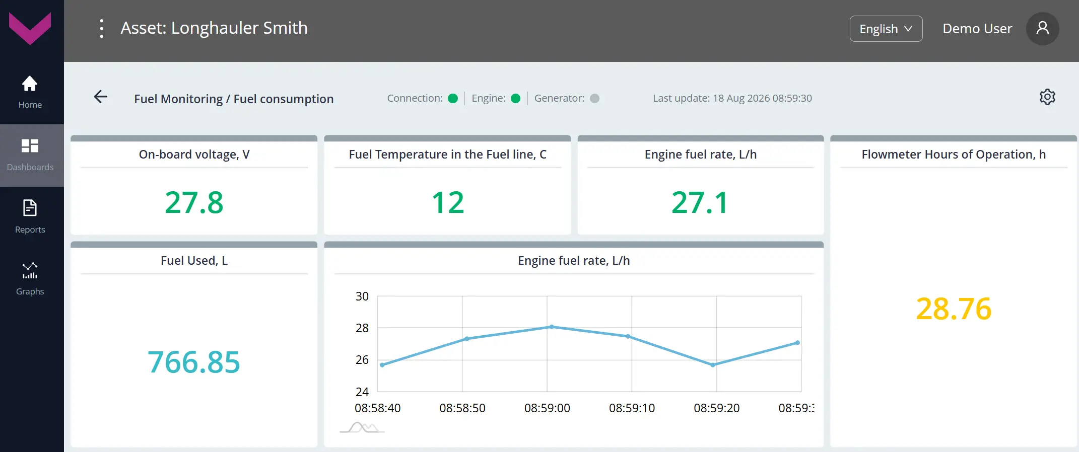
a) real-time data display on the Dashboard *Fuel consumption
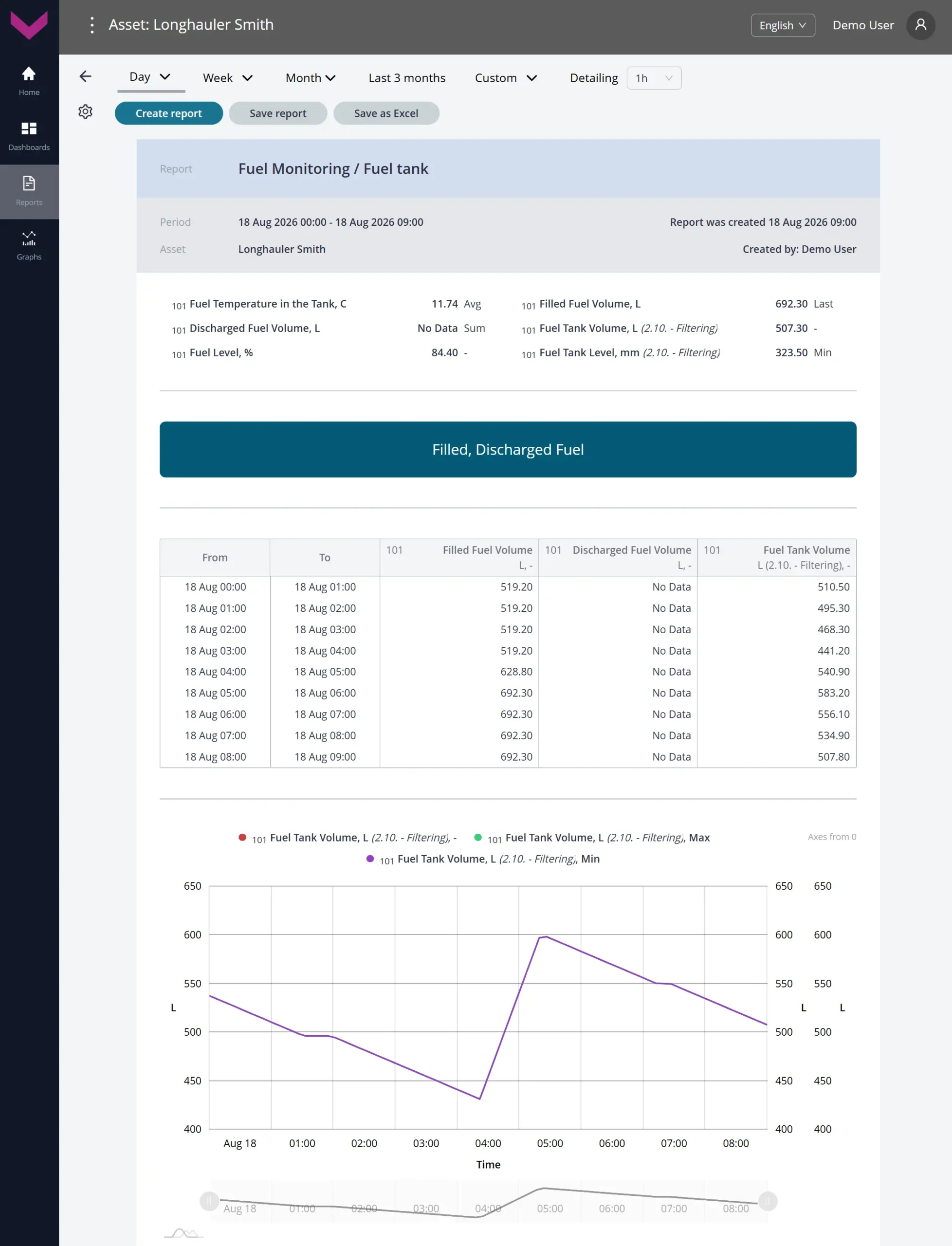
b) Analytical report *Fuel tank for a one-day period
Figure 4 — Examples of data display for Task Fuel Monitoring (MIN)
1.5 Location Tracking #
Class: 25.
Purpose:
Location Tracking — provides real-time tracking and analysis over a selected period of Vehicle position and movement based on GNSS data: latitude, longitude, speed, course, heading, satellite status, and timestamp. The Task enables real-time monitoring of Vehicle movement, review of trip history, and detection of route deviations.
Required Onboard Equipment:
- telematics gateway CANUp 27 Pro (model code 30) – 1 pc.
Industries:
- Fuel & chemicals tankers (code RDF);
- Mining (code MIN).
Role: Operator (code OPR).
Total number of Keys: 25
Occupied Keys: 7 (see Table 5).
Available Keys: 18
Table 5 — Occupied Keys for the Location Tracking Task
| Source network address |
SPN and specifier (if available) |
Unit of measurement |
Explanation |
| 100 | 580 Altitude | m | Altitude of the Vehicle’s current location above sea level, determined from GNSS data. |
| 100 | 584 Latitude | degrees | Latitude coordinate of the Vehicle’s current location, determined from GNSS data. |
| 100 | 585 Longitude | degrees | Longitude coordinate of the Vehicle’s current location, determined from GNSS data. |
| 100 | 521090 HDOP | – | Current HDOP value, a coefficient characterizing the accuracy of the Vehicle’s current position in the horizontal plane. HDOP may range from 1 (maximum accuracy) to 50 (minimum accuracy). |
| 100 | 521126 Distance by GNSS | m | Total distance traveled by the Vehicle since installation of the telematics gateway. This counter can be reset by the user. |
| 100 | 521128 Satellites Quantity | pcs. | Current number of visible navigation satellites. |
| 100 | 521155 UTC Time by GNSS | s | Current time in UTC format, determined from GNSS data. |
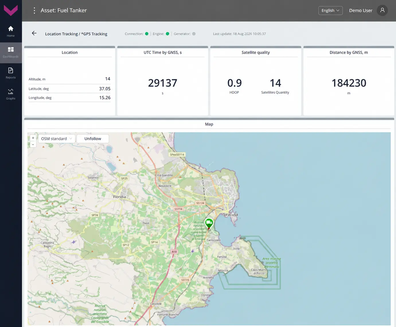
a) real-time data display on the Dashboard *GPS Tracking
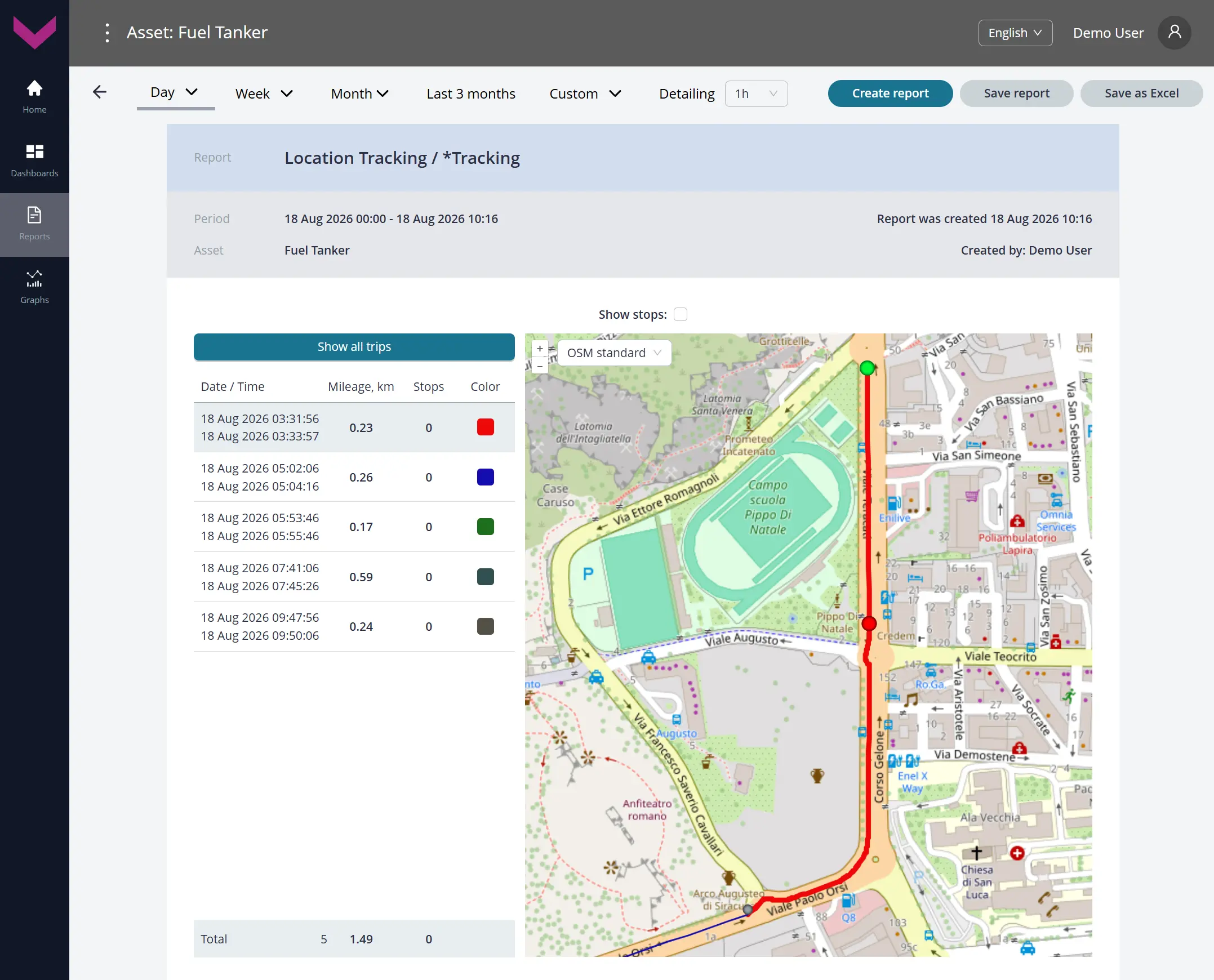
b) Analytical report *Tracking for a one-day period
Figure 5 — Examples of data display for Task Location Tracking
1.6 System Self-Diagnostics (RDF) #
Class: 50.
Purpose:
System Self-Diagnostics (RDF) — provides real-time monitoring and analysis over a selected period of the quality of Onboard Equipment operation, communication lines, power supply, signal quality, device errors, and data availability. The Task enables timely fault detection and monitoring of Telematics System reliability.
Required Onboard Equipment:
- telematics gateway CANUp 27 Pro (model code 30) – 1 pc.
Industry: Fuel & chemicals tankers (code RDF).
Role: Operator (code OPR).
Total number of Keys: 50
Occupied Keys: 30 (see Table 6).
Available Keys: 20
Table 6 — Occupied Keys for the System Self-Diagnostics (RDF) Task
| Source network address |
SPN and specifier (if available) |
Unit of measurement |
Explanation |
| 100 | 158 On-board voltage | V | Current Vehicle onboard power supply voltage reported by the telematics gateway. |
| 100 | 165 Compass Bearing | degrees | Current Vehicle movement direction determined from GNSS data. |
| 100 | 580 Altitude | m | Altitude of the Vehicle’s current location above sea level, determined from GNSS data. |
| 100 | 584 Latitude | degrees | Latitude coordinate of the Vehicle’s current location, determined from GNSS data. |
| 100 | 585 Longitude | degrees | Longitude coordinate of the Vehicle’s current location, determined from GNSS data. |
| 100 | 521050 Battery Level State | – | Current charge status of the telematics gateway built-in battery: fully charged, charging, status cannot be determined, or battery unavailable. |
| 100 | 521055 Vehicle Power Supp.Volt. | V | Current Vehicle onboard power supply voltage. |
| 100 | 521056 Vehicle Power Supp.Stat. | – | Current Vehicle onboard power supply state determined from configured voltage thresholds: off, low level, accumulator, starter, generator, or high level. |
| 100 | 521072 Reports Counter 21. Priority : 2. Information |
– | Number of registered reports for informational Events. |
| 100 | 521072 Reports Counter 21. Priority : 0. Emergency |
– | Number of registered reports for emergency Events. |
| 100 | 521072 Reports Counter 21. Priority : 1. Important |
– | Number of registered reports for important Events. |
| 100 | 521090 HDOP | – | Current HDOP value, a coefficient characterizing the accuracy of the Vehicle position in the horizontal plane. |
| 100 | 521116 Unit Hours Of Operation | s | Counter of total telematics gateway operating time. |
| 100 | 521116 Unit Hours Of Operation 16. Working time from power supply : 1. Battery |
s | Counter of total telematics gateway operating time from the built-in battery. |
| 100 | 521118 Unit Reset Counter 30. Appearance Source : 0. Software |
pcs. | Counter of telematics gateway processor software restarts. |
| 100 | 521118 Unit Reset Counter 30. Appearance Source : 1. Hardware |
pcs. | Counter of telematics gateway hardware restarts caused by power loss or an internal failure. |
| 100 | 521128 Satellites Quantity | pcs. | Current number of visible navigation satellites. |
| 100 | 521129 Unit Power Status | – | Current telematics gateway power status: powered from the built-in source, powered from the onboard network, power off, or status unavailable. |
| 100 | 521134 GNSS Receiver Status | – | Current serviceability status of the telematics gateway built-in GNSS receiver. |
| 100 | 521135 GNSS Antenna Status | – | Current connection status of the telematics gateway built-in GNSS antenna. |
| 100 | 521144 AVL Connection Counter | pcs. | Counter of telematics gateway modem connections to the AVL server. |
| 100 | 521145 AVL Connect.Fail.Counter | pcs. | Counter of failed telematics gateway modem connection attempts to the AVL server. |
| 100 | 521146 AVL Disconnect. Counter | pcs. | Counter of telematics gateway modem disconnections from the AVL server. |
| 100 | 521172 Hours Of Operation From Battery | s | Counter of total telematics gateway operating time from the built-in battery since installation. |
| 100 | 521173 Hours Of Operation On Power Supply | s | Counter of total telematics gateway operating time from the onboard network since installation. |
| 100 | 521176 AVL Authent.Count. | pcs. | Counter of successful telematics gateway authentications on the AVL server. |
| 100 | 521177 AVL Authent.Fail.Count. | pcs. | Counter of failed telematics gateway authentications on the AVL server. |
| 100 | 521178 RSSI | dBm | Current received signal strength (RSSI) of the telematics gateway modem. |
| 100 | 521190 Engn Hours Of Operation | s | Counter of total Vehicle engine operating time over the entire load range. |
| 100 | 521334 GSM Network Mode | – | Current cellular standard used by the telematics gateway built-in GSM modem: 2G, 3G, or 4G. |

a) real-time data display on the Dashboard *GSM signal quality
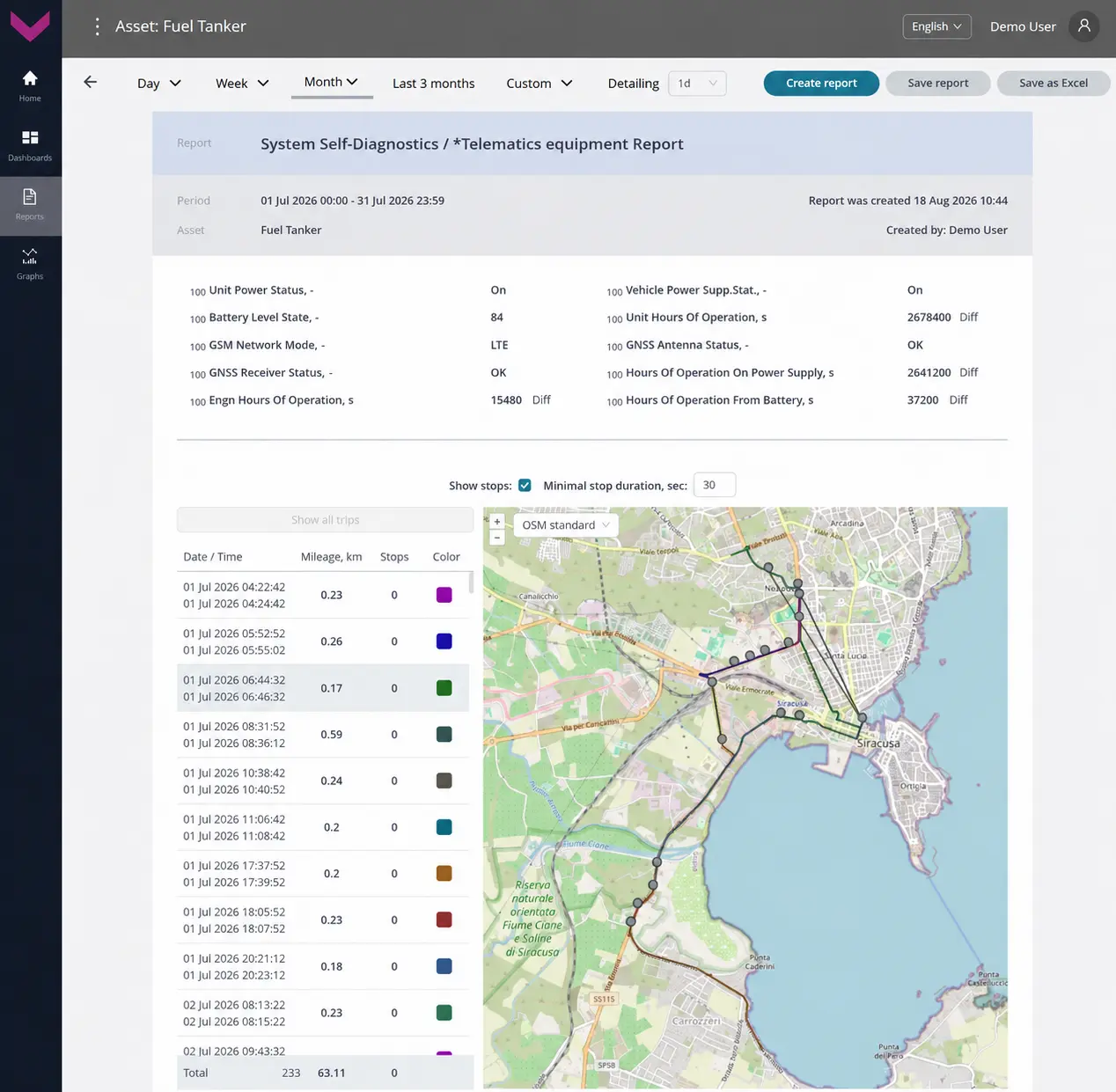
b) Analytical report *Telematics equipment for a one-month period
Figure 6 — Examples of data display for Task System Self-Diagnostics (RDF)
1.7 System Self-Diagnostics (MIN) #
Class: 50.
Purpose:
System Self-Diagnostics (MIN) — provides real-time monitoring and analysis over a selected period of the quality of Onboard Equipment operation: fuel flow meters, fuel level sensors, telematics gateway, converters, communication lines, power supply, signal quality, device errors, and data availability. The Task enables timely fault detection and monitoring of Telematics System reliability.
Required Onboard Equipment:
- telematics gateway CANUp 27 Pro (model code 30) – 1 pc.;
- fuel level sensors DUT-E / DUT-E 2Bio / DUT-E S7 / DUT-E 2Bio S7 – up to 8 pcs.;
- fuel flow meter DFM / DFM D / DFM S7 / DFM D S7 / DFM Marine / DFM Marine S7 – up to 8 pcs.;
- CAN j1939/S6 displays MasterCAN Display 35 – up to 2 pcs.;
- digital-to-analog converter MasterCAN DAC15 – 1 pc.
Industry: Mining (code MIN).
Role: Operator (code OPR).
Total number of Keys: 50
Occupied Keys: 49 (see Table 7).
Available Keys: 1
Table 7 — Occupied Keys for the System Self-Diagnostics (MIN) Task
| Source network address |
SPN and specifier (if available) |
Unit of measurement |
Explanation |
| 100 | 158 On-board voltage | V | Current Vehicle onboard power supply voltage reported by the telematics gateway. |
| 100 | 165 Compass Bearing | degrees | Current Vehicle movement direction determined from GNSS data. |
| 100 | 580 Altitude | m | Altitude of the Vehicle’s current location above sea level, determined from GNSS data. |
| 100 | 584 Latitude | degrees | Latitude coordinate of the Vehicle’s current location, determined from GNSS data. |
| 100 | 585 Longitude | degrees | Longitude coordinate of the Vehicle’s current location, determined from GNSS data. |
| 100 | 521050 Battery Level State | – | Current charge status of the telematics gateway built-in battery: fully charged, charging, status cannot be determined, or battery unavailable. |
| 100 | 521056 Vehicle Power Supp.Stat. | – | Current onboard power supply state determined from configured voltage thresholds: off, low level, accumulator, starter, generator, or high level. |
| 100 | 521072 Reports Counter 21. Priority : 2. Information |
– | Number of registered reports for informational Events. |
| 100 | 521072 Reports Counter 21. Priority : 0. Emergency |
– | Number of registered reports for emergency Events. |
| 100 | 521072 Reports Counter 21. Priority : 1. Important |
– | Number of registered reports for important Events. |
| 100 | 521090 HDOP | – | Current HDOP value, a coefficient characterizing the accuracy of the Vehicle position in the horizontal plane. |
| 100 | 521116 Unit Hours Of Operation | s | Counter of total telematics gateway operating time. |
| 100 | 521116 Unit Hours Of Operation 16. Working time from power supply : 1. Battery |
s | Counter of total telematics gateway operating time from the built-in battery. |
| 100 | 521118 Unit Reset Counter 30. Appearance Source : 0. Software |
pcs. | Counter of telematics gateway processor software restarts. |
| 100 | 521118 Unit Reset Counter 30. Appearance Source : 1. Hardware |
pcs. | Counter of telematics gateway hardware restarts caused by power loss or an internal failure. |
| 100 | 521128 Satellites Quantity | pcs. | Current number of visible navigation satellites. |
| 100 | 521129 Unit Power Status | – | Current telematics gateway power status: powered from the built-in source, powered from the onboard network, power off, or status unavailable. |
| 100 | 521134 GNSS Receiver Status | – | Current serviceability status of the telematics gateway built-in GNSS receiver. |
| 100 | 521135 GNSS Antenna Status | – | Current connection status of the telematics gateway built-in GNSS antenna. |
| 100 | 521144 AVL Connection Counter | pcs. | Counter of telematics gateway modem connections to the AVL server. |
| 100 | 521145 AVL Connect.Fail.Counter | pcs. | Counter of telematics gateway modem connection errors to the AVL server. |
| 100 | 521146 AVL Disconnect. Counter | pcs. | Counter of telematics gateway modem disconnections from the AVL server. |
| 100 | 521172 Hours Of Operation From Battery | s | Counter of total operating time in battery power mode since installation of the telematics gateway. |
| 100 | 521173 Hours Of Operation On Power Supply | s | Counter of total operating time in onboard network power mode since installation of the telematics gateway. |
| 100 | 521176 AVL Authent.Count. | pcs. | Counter of successful telematics gateway authentications on the AVL server. |
| 100 | 521177 AVL Authent.Fail.Count. | pcs. | Counter of telematics gateway authentication errors on the AVL server. |
| 100 | 521178 RSSI | dBm | Current signal strength (RSSI) received by the telematics gateway modem. |
| 100 | 521190 Engn Hours Of Operation | s | Counter of total engine operating time over the entire load range. |
| 100 | 521334 GSM Network Mode | – | Current cellular standard used by the telematics gateway built-in GSM modem (2G/3G/4G). |
| 100 | 521488 Unit DTCs Mask | – | Bit mask of diagnostic trouble codes for the telematics gateway. |
| 101 | 521488 Unit DTCs Mask | – | Bit mask of diagnostic trouble codes for fuel level sensor No. 1. |
| 102 | 521488 Unit DTCs Mask | – | Bit mask of diagnostic trouble codes for fuel level sensor No. 2. |
| 103 | 521488 Unit DTCs Mask | – | Bit mask of diagnostic trouble codes for fuel level sensor No. 3. |
| 104 | 521488 Unit DTCs Mask | – | Bit mask of diagnostic trouble codes for fuel level sensor No. 4. |
| 105 | 521488 Unit DTCs Mask | – | Bit mask of diagnostic trouble codes for fuel level sensor No. 5. |
| 106 | 521488 Unit DTCs Mask | – | Bit mask of diagnostic trouble codes for fuel level sensor No. 6. |
| 107 | 521488 Unit DTCs Mask | – | Bit mask of diagnostic trouble codes for fuel level sensor No. 7. |
| 108 | 521488 Unit DTCs Mask | – | Bit mask of diagnostic trouble codes for fuel level sensor No. 8. |
| 111 | 521488 Unit DTCs Mask | – | Bit mask of diagnostic trouble codes for fuel flow meter No. 1. |
| 112 | 521488 Unit DTCs Mask | – | Bit mask of diagnostic trouble codes for fuel flow meter No. 2. |
| 113 | 521488 Unit DTCs Mask | – | Bit mask of diagnostic trouble codes for fuel flow meter No. 3. |
| 114 | 521488 Unit DTCs Mask | – | Bit mask of diagnostic trouble codes for fuel flow meter No. 4. |
| 115 | 521488 Unit DTCs Mask | – | Bit mask of diagnostic trouble codes for fuel flow meter No. 5. |
| 116 | 521488 Unit DTCs Mask | – | Bit mask of diagnostic trouble codes for fuel flow meter No. 6. |
| 117 | 521488 Unit DTCs Mask | – | Bit mask of diagnostic trouble codes for fuel flow meter No. 7. |
| 118 | 521488 Unit DTCs Mask | – | Bit mask of diagnostic trouble codes for fuel flow meter No. 8. |
| 109 | 521488 Unit DTCs Mask | – | Bit mask of diagnostic trouble codes for CAN display No. 1. |
| 110 | 521488 Unit DTCs Mask | – | Bit mask of diagnostic trouble codes for CAN display No. 2. |
| 126 | 521488 Unit DTCs Mask | – | Bit mask of diagnostic trouble codes for the digital-to-analog converter. |
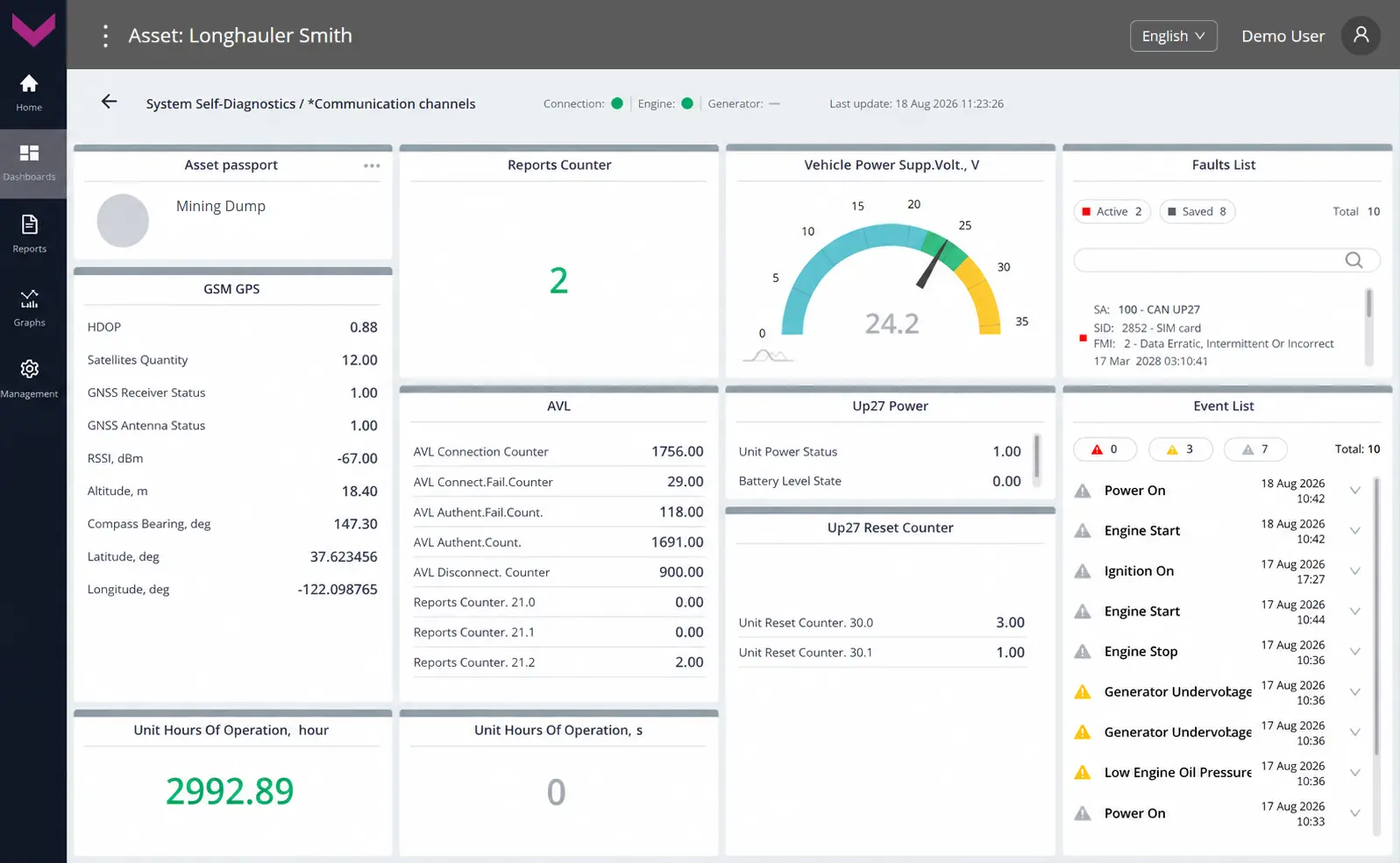
a) real-time data display on the Dashboard *Communication channels
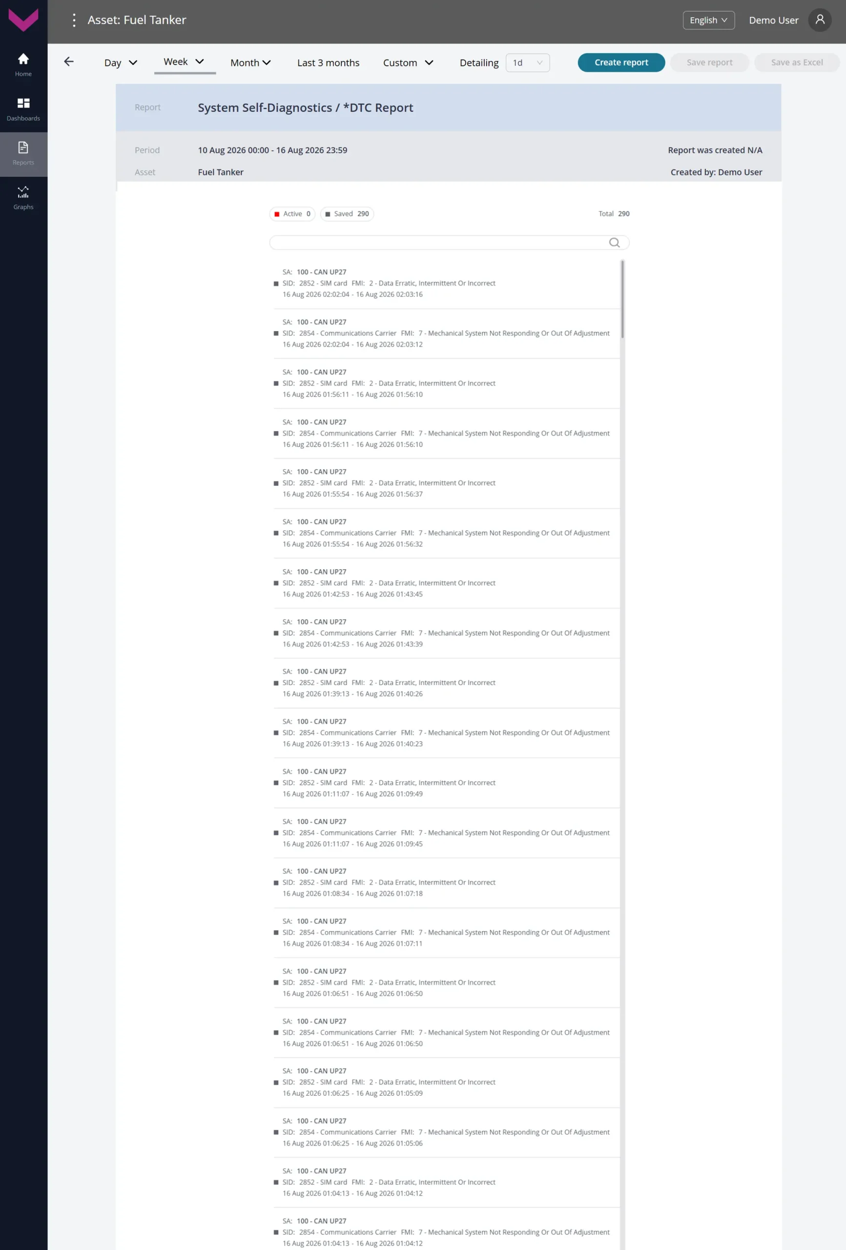
b) Analytical report *DTC Report for a one-week period
Figure 7 — Examples of data display for Task System Self-Diagnostics (MIN)
1.8 Maintenance #
Class: 25.
Purpose:
Maintenance — provides real-time and historical analysis over a selected period of Vehicle operating patterns to optimize maintenance schedules and improve overall operational efficiency. The Task enables timely maintenance planning, helps keep the Vehicle and Onboard Equipment in proper working condition, and improves their operational reliability.
Required Onboard Equipment:
- telematics gateway CANUp 27 Pro (model code 30) – 1 pc.;
- contactless reader CANCrocodile – 1 pc.;
- fuel flow meter DFM / DFM D / DFM S7 / DFM D S7 – 1 pc.
Industries:
- Fuel & chemicals tankers (code RDF);
- Mining (code MIN).
Role: Operator (code OPR).
Total number of Keys: 25
Occupied Keys: 13 (see Table 8).
Available Keys: 12
Table 8 — Occupied Keys for the Maintenance Task
| Source network address |
SPN and specifier (if available) |
Unit of measurement |
Explanation |
| 0 | 100 Oil pressure | kPa | Current engine oil pressure. |
| 0 | 110 Coolant temp | °C | Current engine coolant temperature. |
| 100 | 158 On-board voltage | V | Current onboard power supply voltage reported by the telematics gateway. |
| 0 | 190 Engine RPM | rpm | Current engine crankshaft speed. |
| 100 | 521001 Tot.Engn Starts Count. | pcs. | Counter of total engine starts. The user can reset the counter. |
| 100 | 521006 Exceed.Start.Time Count. | pcs. | Counter of engine starts exceeding the maximum allowable continuous starter operating time. Cannot be reset by the user. |
| 100 | 521007 Engn Start Fail. Count. | pcs. | Counter of unsuccessful engine starts. Cannot be reset by the user. |
| 100 | 521072 Reports Counter | pcs. | Current number of registered reports. |
| 100 | 521076 Vehicle Power Supp.Pres. | – | Current onboard power supply state (On/Off) based on the user-defined voltage cutoff threshold. |
| 100 | 521116 Unit Hours Of Operation | s | Counter of total telematics gateway operating time. |
| 111 | 521116 Unit Hours Of Operation | s | Counter of total flow meter operating time. |
| 100 | 521190 Engn Hours Of Operation | s | Counter of total engine operating time over the entire load range, including idle operation. The user can reset the counter. |
| 100 | 521488 Unit DTCs Mask | – | Bit mask of diagnostic trouble codes for the telematics gateway. |
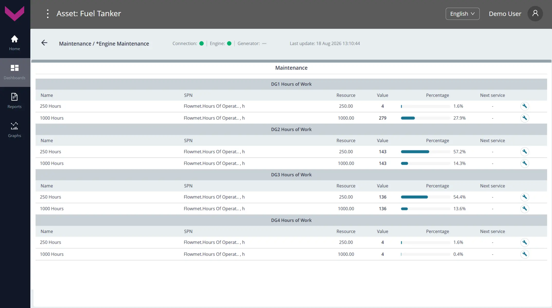
a) real-time data display on the Dashboard *Engine Maintenance
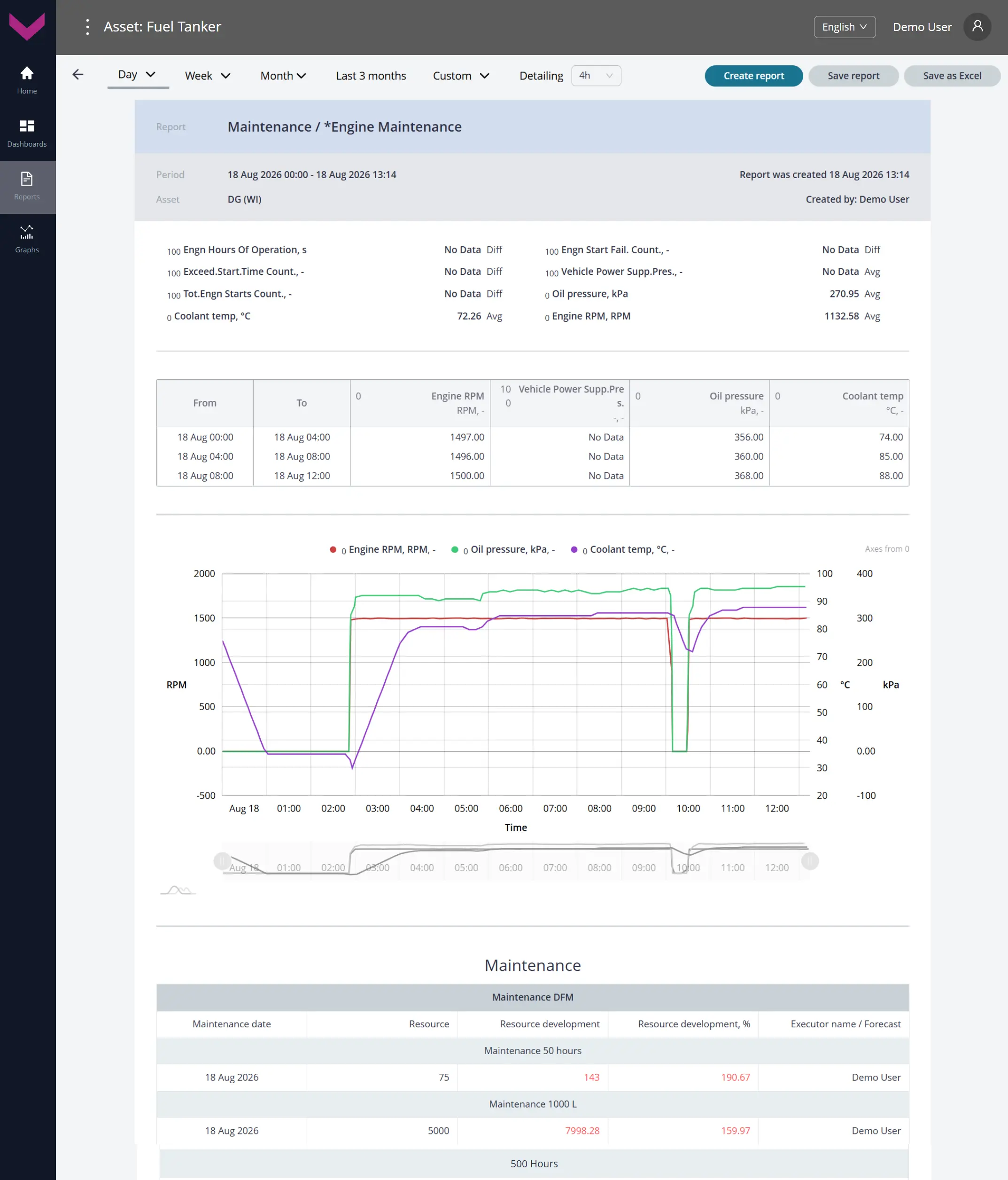
b) Analytical report *Engine Maintenance for a one-day period
Figure 8 — Examples of data display for Task Maintenance
2 Tasks for Groups #
2.1 Group. Axle Load Monitoring #
Class: 25.
Purpose:
Group. Axle Load Monitoring — provides Group-level monitoring of axle loads across multiple Vehicles using pressure sensors for air suspension or displacement sensors for leaf-spring suspension. The Task enables monitoring of axle loads, total Vehicle load, overload Events, load distribution, and load changes during loading and unloading at Group level.
Required Onboard Equipment:
- telematics gateway CANUp 27 Pro (model code 30) – 20 pcs.;
- axle load sensors GNOM DP CAN / GNOM DP S7 / GNOM DDE S7 – 40 pcs.
Industry: UNUM (code UNM).
Role: Operator (code OPR).
Total number of Keys: 25
Occupied Keys: 13 (see Table 9).
Available Keys: 12
Table 9 — Occupied Keys for the Group. Axle Load Monitoring Task
| Source network address* |
SPN and specifier (if available) |
Unit of measurement |
Explanation |
| 1000 | 582 Axle load | kg | Current axle load of Vehicles in the Group. |
| 82** | 582 Axle load 17. At Event moment : 0. At the Event start |
kg | Vehicle axle load at the start of a loading / unloading Event. |
| 82** | 582 Axle load 17. At Event moment : 1. At the Event end |
kg | Vehicle axle load at the end of a loading / unloading Event. |
| 1000 | 5347 Lateral Acceleration Extended Range | m/s² | Current lateral acceleration measured by the axle load sensors of Vehicles in the Group. |
| 1000 | 5348 Longitudinal Acceleration Extended Range | m/s² | Current longitudinal acceleration measured by the axle load sensors of Vehicles in the Group. |
| 1000 | 5349 Vertical Acceleration Extended Range | m/s² | Current vertical acceleration measured by the axle load sensors of Vehicles in the Group. |
| 1000 | 521036 Overload Counter | pcs. | Counter of registered Vehicle overload Events in the Group. |
| 1000 | 521037 Load Counter | pcs. | Counter of registered Vehicle loading Events in the Group. |
| 1000 | 521038 Unloading Counter | pcs. | Counter of registered Vehicle unloading Events in the Group. |
| 1000 | 521182 Axle Weight Mode | – | Current loading mode of Vehicles in the Group (Empty / Optimal / Maximal / Overload). |
| 1000 | 521469 Angle | degrees | Current pivot lever deviation angle of the axle load sensors of Vehicles in the Group. |
| 1000 | 521511 Suspension Air Pressure | kPa | Current air pressure in the air suspension of Vehicles in the Group. |
| 1000 | 521513 Suspension Air Temperature | °C | Current air temperature in the air suspension of Vehicles in the Group. |
| * The source network address (SA) of each Key for Group Tasks is always set to 1000, regardless of the source network addresses of similar Keys for individual Assets within the Group. ** The specific network address of the axle load sensor that is the source Unit of the registered Event on the corresponding Vehicle in the Group. |
|||
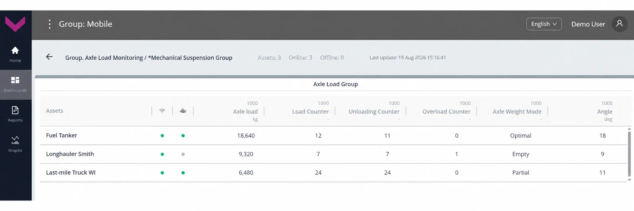
a) real-time data display on the Dashboard *Mechanical Suspension Group
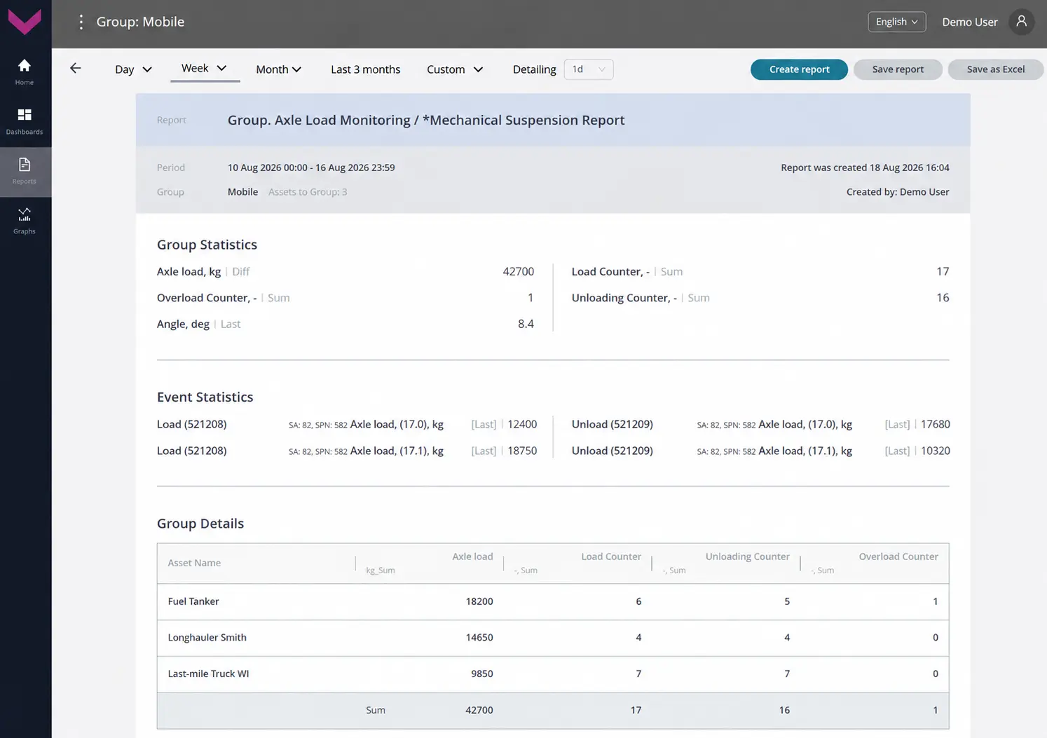
b) Analytical report *Mechanical Suspension Report for a one-week period
Figure 9 — Examples of data display for Task Group. Axle Load Monitoring
2.2 Group. Cargo Tanks Monitoring #
Class: 25.
Purpose:
Group. Cargo Tanks Monitoring — provides real-time monitoring at Group level and analysis over a selected period of fuel Parameters in fuel tanker compartments. The Task enables monitoring of fuel level, volume, temperature, and relative permittivity, assessment of compartment filling, recording of fuel loading and unloading Events in tanker compartments, monitoring of delivery balance, and detection of abnormal changes in fuel quantity at Group level.
Required Onboard Equipment:
- telematics gateway CANUp 27 Pro (model code 30) – 20 pcs.;
- fuel level sensor DUT-E / DUT-E 2Bio / DUT-E S7 / DUT-E 2Bio S7 – 80 pcs.
Industry: UNUM (code UNM).
Role: Operator (code OPR).
Total number of Keys: 25
Occupied Keys: 9 (see Table 10).
Available Keys: 16
Table 10 — Occupied Keys for the Group. Cargo Tanks Monitoring Task
| Source network address* |
SPN and specifier (if available) |
Unit of measurement |
Explanation |
| 1000 | 521023 Fuel Tank Level | mm | Current fuel level height in the tanker compartments of Vehicles in the Group. |
| 101** | 521024 Fuel Tank Volume 17. At Event moment : 0. At the Event start |
l | Fuel volume in a Vehicle tanker compartment at the start of a loading / unloading Event. |
| 101** | 521024 Fuel Tank Volume 17. At Event moment : 1. At the Event end |
l | Fuel volume in a Vehicle tanker compartment at the end of a loading / unloading Event. |
| 101** | 521300 Event Date/Time | s | Date and time of a loading / unloading Event detected from the fuel level sensor data of the corresponding tanker compartment. |
| 1000 | 521301 Filled Fuel Volume | l | Fuel volume loaded into a tanker compartment during a registered loading Event for a Vehicle in the Group. |
| 1000 | 521302 Discharged Fuel Volume | l | Fuel volume unloaded from a tanker compartment during a registered unloading Event for a Vehicle in the Group. |
| 1000 | 521457 Temperature | °C | Current fuel temperature in the tanker compartments of Vehicles in the Group. |
| 1000 | 521728 Fuel Tank Volume | l | Current fuel volume in the tanker compartments of Vehicles in the Group. |
| 1000 | 521774 Fuel Permittivity Relative | – | Current relative permittivity of fuel in the tanker compartments of Vehicles in the Group, used to identify the fuel type. |
| * The source network address (SA) of each Key for Group Tasks is always set to 1000, regardless of the source network addresses of similar Keys for individual Assets within the Group. ** The specific network address of the fuel level sensor that is the source Unit of the registered tanker loading / unloading Event on the corresponding Vehicle in the Group. |
|||
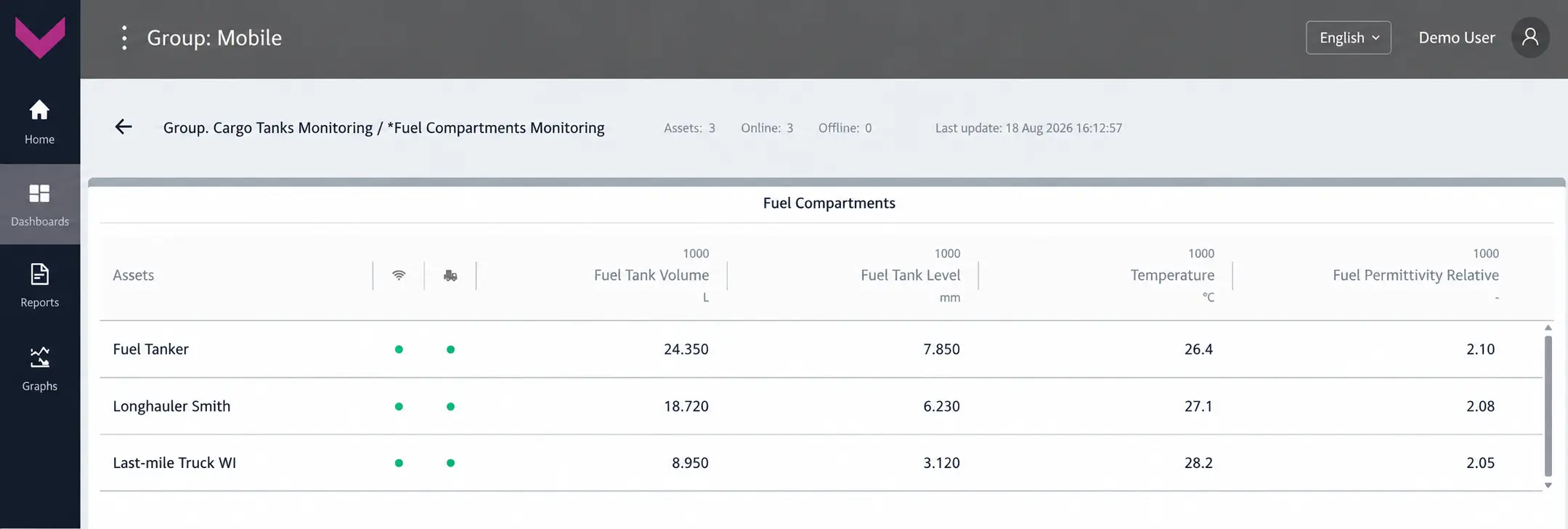
a) real-time data display on the Dashboard *Fuel Compartments Monitoring
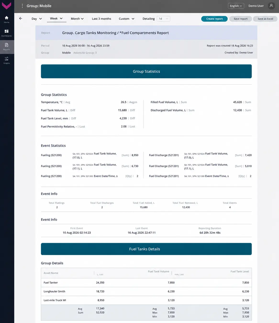
b) Analytical report *Fuel Compartments Report for a one-week period
Figure 10 — Examples of data display for Task Group. Cargo Tanks Monitoring
2.3 Group. Engine Performance #
Class: 25.
Purpose:
Group. Engine Performance — provides real-time monitoring at Group level and analysis over a selected period of Vehicle engine operating Parameters received from onboard CAN buses: engine speed, load, exhaust gas and coolant temperatures, oil pressure and temperature, engine hours, operating status, fault codes, and alarms. The Task provides a unified view for comparing engine operation and detecting abnormal operating conditions at Group level.
Required Onboard Equipment:
- telematics gateway CANUp 27 Pro (model code 30) – 20 pcs.;
- contactless reader CANCrocodile – 40 pcs.
Industry: UNUM (code UNM).
Role: Operator (code OPR).
Total number of Keys: 25
Occupied Keys: 10 (see Table 11).
Available Keys: 15
Table 11 — Occupied Keys for the Group. Engine Performance Task
| Source network address* |
SPN and specifier (if available) |
Unit of measurement |
Explanation |
| 1000 | 98 Engine Oil Level | % | Current engine oil level of Vehicles in the Group. |
| 1000 | 100 Oil pressure | kPa | Current engine oil pressure of Vehicles in the Group. |
| 1000 | 110 Coolant temp | °C | Current engine coolant temperature of Vehicles in the Group. |
| 1000 | 111 Engine Coolant Lvl | % | Current engine coolant level of Vehicles in the Group. |
| 1000 | 173 Engn Exhst Gas Tmp | °C | Current engine exhaust gas temperature of Vehicles in the Group. |
| 1000 | 175 Engn Oil Tmp | °C | Current engine oil temperature of Vehicles in the Group. |
| 1000 | 190 Engine RPM | rpm | Current engine crankshaft speed of Vehicles in the Group. |
| 1000 | 247 Engine hours | h | Total engine operating time of Vehicles in the Group. |
| 1000 | 3543 Engine Operating State | – | Current engine operating state of Vehicles in the Group (off / starting / running / stopping / idle / start error). |
| 1000 | 521300 Event Date/Time | s | Date and time of an Event recorded by the engine ECU of the corresponding Vehicle in the Group (for example, DTC activation, engine start / stop, temperature threshold exceeded, etc.). |
| * The source network address (SA) of each Key for Group Tasks is always set to 1000, regardless of the source network addresses of similar Keys for individual Assets within the Group. | |||
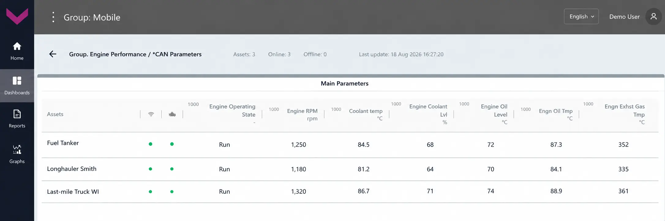
a) real-time data display on the Dashboard *CAN Parameters
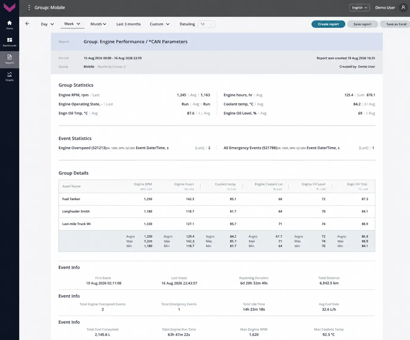
b) Analytical report *CAN Parameters for a one-week period
Figure 11 — Examples of data display for Task Group. Engine Performance
2.4 Group. Fuel Monitoring #
Class: 25.
Purpose:
Group. Fuel Monitoring — provides real-time monitoring at Group level and analysis over a selected period of fuel level and volume in Vehicle tanks, fuel temperature, hourly and total fuel consumption, flow meter operating time, and fuel-system Events. The Task enables comparison of fuel consumption across Vehicles, monitoring of refueling and draining, detection of interference, abnormal consumption and possible losses, and evaluation of CO₂ emissions at Group level.
Required Onboard Equipment:
- telematics gateway CANUp 27 Pro (model code 30) – 20 pcs.;
- fuel level sensor DUT-E / DUT-E 2Bio / DUT-E S7 / DUT-E 2Bio S7 – 20 pcs.;
- fuel flow meter DFM / DFM D / DFM S7 / DFM D S7 – 20 pcs.
Industry: UNUM (code UNM).
Role: Operator (code OPR).
Total number of Keys: 25
Occupied Keys: 18 (see Table 12).
Available Keys: 7
Table 12 — Occupied Keys for the Group. Fuel Monitoring Task
| Source network address* |
SPN and specifier (if available) |
Unit of measurement |
Explanation |
| 1000 | 96 Fuel Level | % | Current fuel level in Vehicle tanks across the Group, expressed as a percentage of full-tank level. |
| 1000 | 158 On-board voltage | V | Current on-board network voltage reported by fuel monitoring equipment across the Group. |
| 1000 | 174 Engine Fuel Temp | °C | Current fuel temperature reported by fuel monitoring equipment across the Group. |
| 1000 | 183 Engine fuel rate | l/h | Current hourly engine fuel consumption across the Group; for a differential flow meter, differential consumption through both measuring chambers. |
| 1000 | 5054 High Res.Total Fuel Used | l | Total engine fuel consumption across Vehicles in the Group over the entire load range. |
| 1000 | 521023 Fuel Tank Level 2. Mathematical processing : 10. Filtering |
mm | Filtered fuel level height in Vehicle tanks across the Group. |
| 1000 | 521024 Fuel Tank Volume 2. Mathematical processing : 10. Filtering |
l | Filtered fuel volume in Vehicle tanks across the Group. |
| 101** | 521024 Fuel Tank Volume 17. At Event moment : 0. At the Event start |
l | Fuel volume in the Vehicle tank at the start of a refueling / draining Event. |
| 101** | 521024 Fuel Tank Volume 17. At Event moment : 1. At the Event end |
l | Fuel volume in the Vehicle tank at the end of a refueling / draining Event. |
| 1000 | 521171 Flowmet.Hours Of Operat. | s | Total operating time of Vehicle fuel flow meters across the Group. |
| 101** | 521300 Event Date/Time | s | Date and time of a refueling / draining Event detected from the corresponding Vehicle fuel level sensor. |
| 111*** | 521300 Event Date/Time | s | Date and time of a fuel-system Event recorded by the corresponding flow meter. |
| 1000 | 521301 Filled Fuel Volume | l | Fuel volume added to Vehicle tanks in the Group during refueling Events. |
| 1000 | 521302 Discharged Fuel Volume | l | Fuel volume drained from Vehicle tanks in the Group during draining Events. |
| 111*** | 521309 Cheating Fuel Volume | l | Simulated fuel consumption volume recorded during a “Cheating” Event affecting the corresponding flow meter. |
| 111*** | 521310 Interference Duration | s | Duration of interference with the corresponding flow meter when an “Interference” Event is registered. |
| 1000 | 521864 Total CO2 Emission | kg | Total engine CO₂ emissions of Vehicles in the Group, calculated from total fuel consumption. |
| 1000 | 521865 Hourly CO2 Emission | kg/h | Hourly engine CO₂ emissions of Vehicles in the Group, calculated from hourly fuel consumption. |
| * The source network address (SA) of each Key for Group Tasks is always set to 1000, regardless of the source network addresses of similar Keys for individual Assets within the Group. ** The specific network address of the fuel level sensor that is the source Unit of the registered refueling / draining Event on the corresponding Vehicle in the Group. *** The specific network address of the fuel flow meter that is the source Unit of the registered “Cheating” / “Interference” Event on the corresponding Vehicle in the Group. |
|||
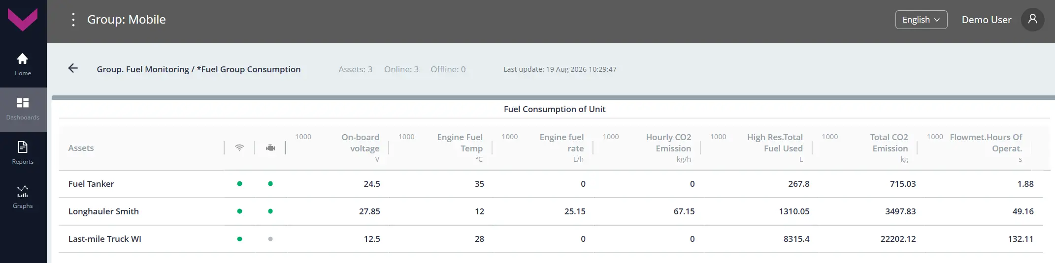
a) real-time data display on the Dashboard *Fuel Group Consumption
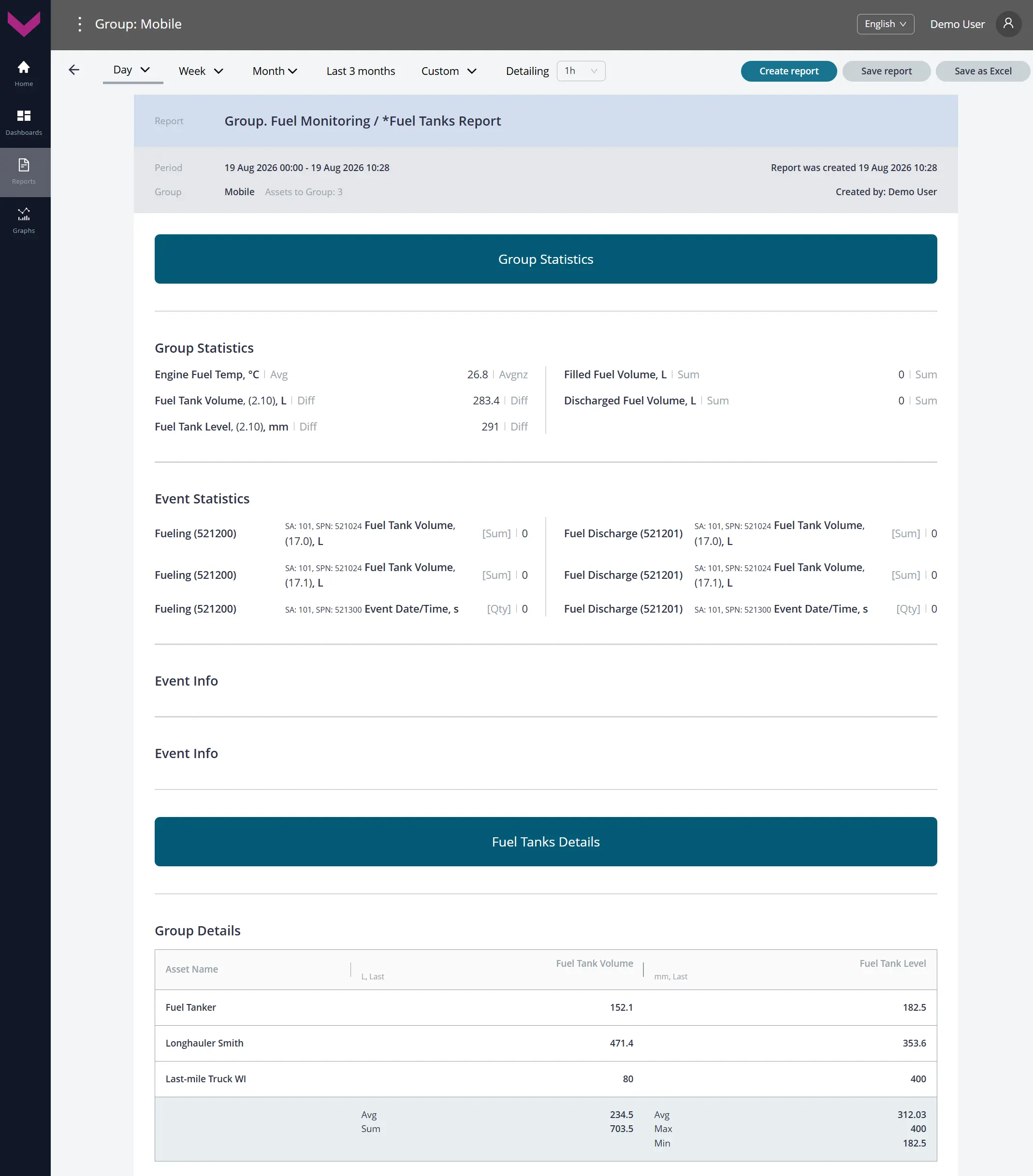
b) Analytical report *Fuel Tanks Report for a one-day period
Figure 12 — Examples of data display for Task Group. Fuel Monitoring
2.5 Group. System Self-Diagnostics #
Class: 25.
Purpose:
Group. System Self-Diagnostics — provides real-time monitoring at Group level and analysis over a selected period of the status of Vehicle Onboard Equipment: fuel flow meters, fuel level sensors, telematics gateways, converters, communication lines, power supply, signal quality, device diagnostic trouble codes, and data availability. The Task provides a unified view of Telematics System status across Vehicles in the Group, enables timely fault detection, and supports monitoring of Onboard Equipment reliability.
Required Onboard Equipment:
- telematics gateway CANUp 27 Pro (model code 30) – 20 pcs.;
- fuel level sensors DUT-E / DUT-E 2Bio / DUT-E S7 / DUT-E 2Bio S7 – up to 160 pcs.;
- fuel flow meter DFM / DFM D / DFM S7 / DFM D S7 / DFM Marine / DFM Marine S7 – up to 160 pcs.;
- CAN j1939/S6 displays MasterCAN Display 35 – up to 40 pcs.;
- digital-to-analog converter MasterCAN DAC15 – 20 pcs.
Industry: UNUM (code UNM).
Role: Operator (code OPR).
Total number of Keys: 25
Occupied Keys: 21 (see Table 13).
Available Keys: 4
Table 13 — Occupied Keys for the Group. System Self-Diagnostics Task
| Source network address* |
SPN and specifier (if available) |
Unit of measurement |
Explanation |
| 1000 | 158 On-board voltage | V | Current onboard power supply voltage of Vehicles in the Group reported by the corresponding telematics gateways. |
| 1000 | 521050 Battery Level State | – | Current charge status of the built-in batteries of Vehicle telematics gateways in the Group: fully charged, charging, status cannot be determined, or battery unavailable. |
| 1000 | 521056 Vehicle Power Supp.Stat. | – | Current onboard power supply state of Vehicles in the Group determined from configured voltage thresholds: off, low level, accumulator, starter, generator, or high level. |
| 1000 | 521072 Reports Counter | pcs. | Current number of registered reports for Vehicles in the Group. |
| 1000 | 521072 Reports Counter 21. Priority : 0. Emergency |
– | Number of registered emergency Event reports for Vehicles in the Group. |
| 1000 | 521072 Reports Counter 21. Priority : 1. Important |
– | Number of registered important Event reports for Vehicles in the Group. |
| 1000 | 521116 Unit Hours Of Operation | s | Counter of total operating time of Vehicle telematics gateways in the Group. |
| 1000 | 521116 Unit Hours Of Operation 16. Working time from power supply : 1. Battery |
s | Counter of total operating time of Vehicle telematics gateways in the Group from their built-in batteries. |
| 1000 | 521118 Unit Reset Counter | pcs. | Counter of total telematics gateway restarts for Vehicles in the Group. |
| 1000 | 521129 Unit Power Status | – | Current power status of Vehicle telematics gateways in the Group: powered from the built-in source, powered from the onboard network, power off, or status unavailable. |
| 1000 | 521134 GNSS Receiver Status | – | Current serviceability status of the built-in GNSS receivers of Vehicle telematics gateways in the Group. |
| 1000 | 521135 GNSS Antenna Status | – | Current connection status of the built-in GNSS antennas of Vehicle telematics gateways in the Group. |
| 1000 | 521144 AVL Connection Counter | pcs. | Counter of modem connections of Vehicle telematics gateways in the Group to the AVL server. |
| 1000 | 521145 AVL Connect.Fail.Counter | pcs. | Counter of failed modem connections of Vehicle telematics gateways in the Group to the AVL server. |
| 1000 | 521146 AVL Disconnect. Counter | pcs. | Counter of modem disconnections of Vehicle telematics gateways in the Group from the AVL server. |
| 1000 | 521173 Hours Of Operation On Power Supply | s | Counter of total operating time of Vehicle telematics gateways in the Group from the onboard network since installation. |
| 1000 | 521176 AVL Authent.Count. | pcs. | Counter of successful authentications of Vehicle telematics gateways in the Group on the AVL server. |
| 1000 | 521177 AVL Authent.Fail.Count. | pcs. | Counter of failed authentications of Vehicle telematics gateways in the Group on the AVL server. |
| 1000 | 521190 Engn Hours Of Operation | s | Counter of total engine operating time of Vehicles in the Group over the entire load range. |
| 1000 | 521334 GSM Network Mode | – | Current cellular standard (2G/3G/4G) used by the built-in GSM modems of Vehicle telematics gateways in the Group. |
| 1000 | 521488 Unit DTCs Mask | – | Bit mask of diagnostic trouble codes for Vehicle telematics gateways in the Group. |
| * The source network address (SA) of each Key for Group Tasks is always set to 1000, regardless of the source network addresses of similar Keys for individual Assets within the Group. | |||
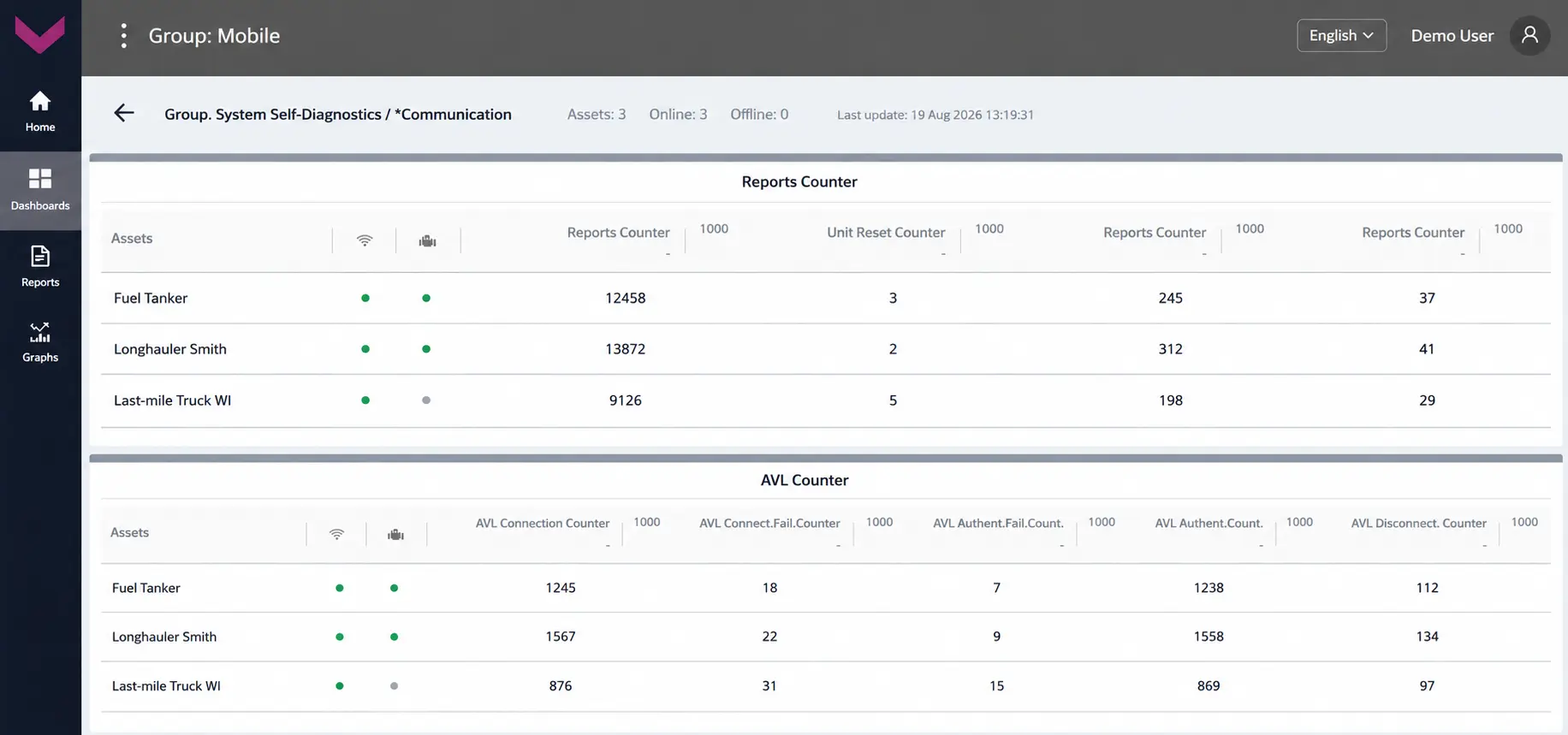
a) real-time data display on the Dashboard *Communication
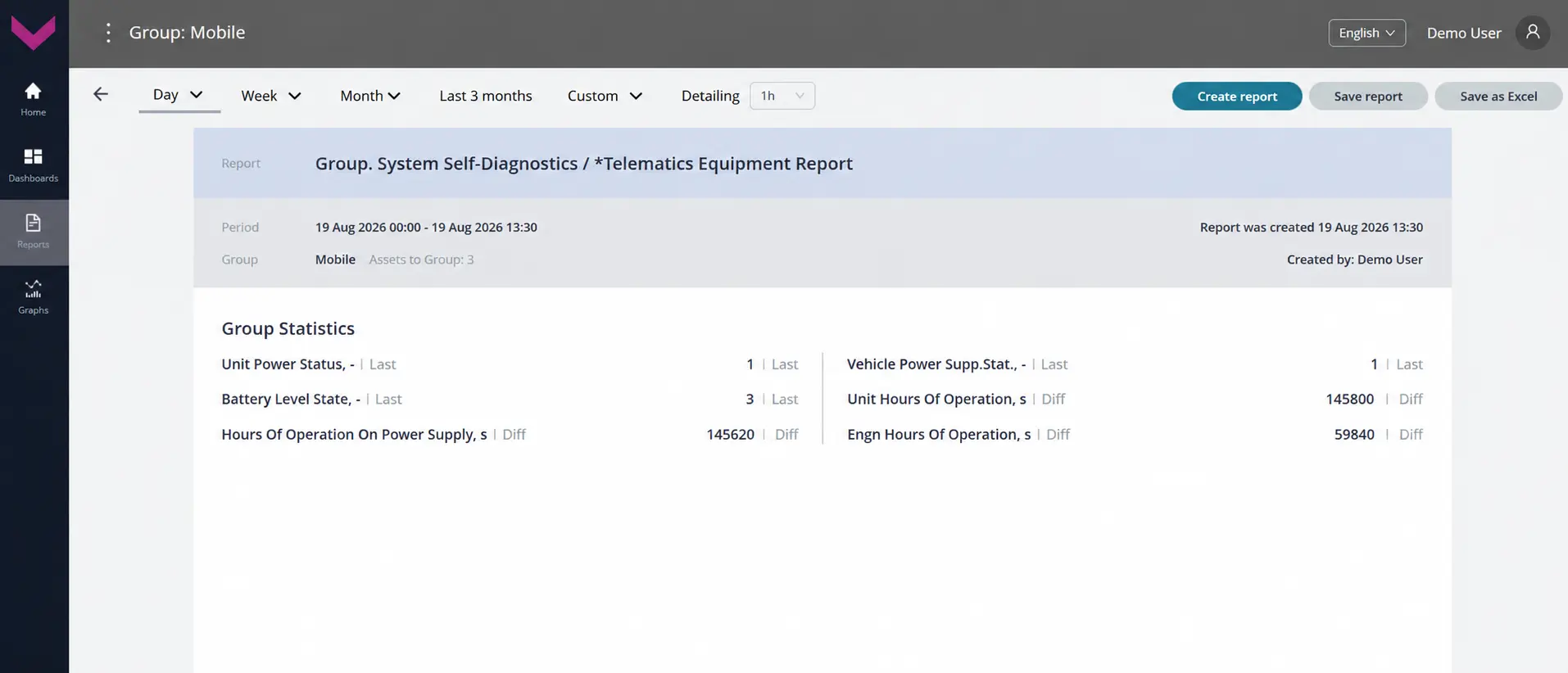
b) Analytical report *Telematics Equipment Report for a one-day period
Figure 13 — Examples of data display for Task Group. System Self-Diagnostics
3 Tasks for Geofences #
3.1 Geofence Statistics #
Class: 25.
Purpose:
Geofence Statistics — provides real-time monitoring and analysis over a selected period of Vehicle activity within a defined Geofence: entry and exit Events with determination of the corresponding points, time spent within the Geofence, and number of visits. Indicators for each Vehicle are calculated automatically based on a standard set of navigation data received from the corresponding telematics gateway.
Required Onboard Equipment:
- telematics gateway CANUp 27 Pro (model code 30) – any quantity.
Industry: UNUM (code UNM).
Role: Operator (code OPR).
Total number of Keys: 25
Adding Keys is not available.
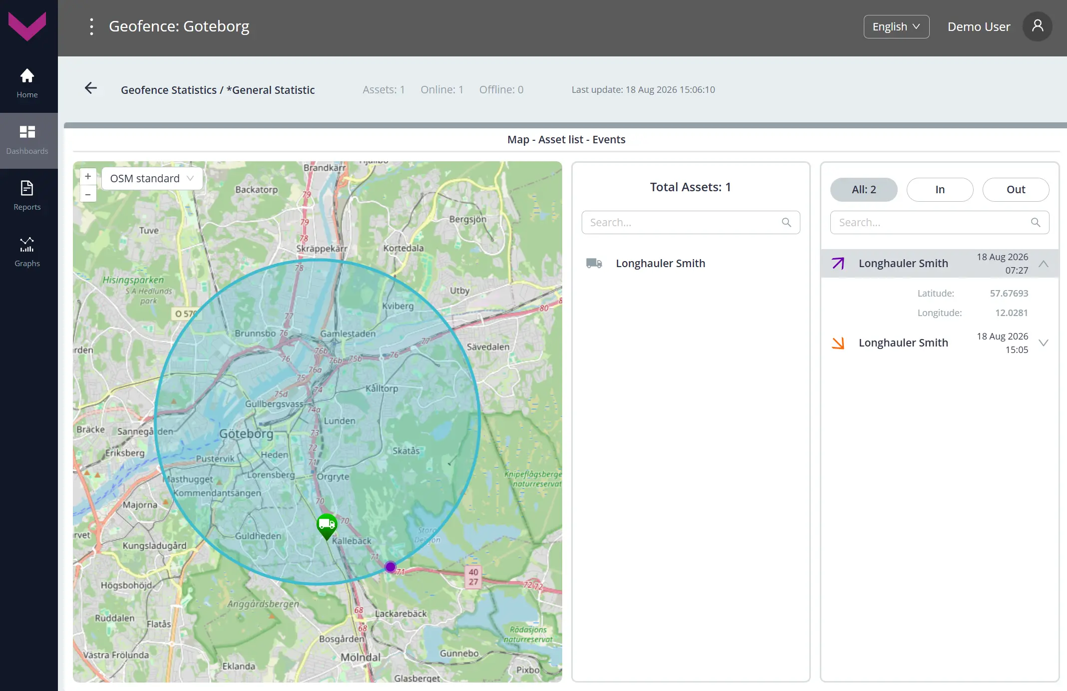
a) real-time data display on the Dashboard *General Statistic
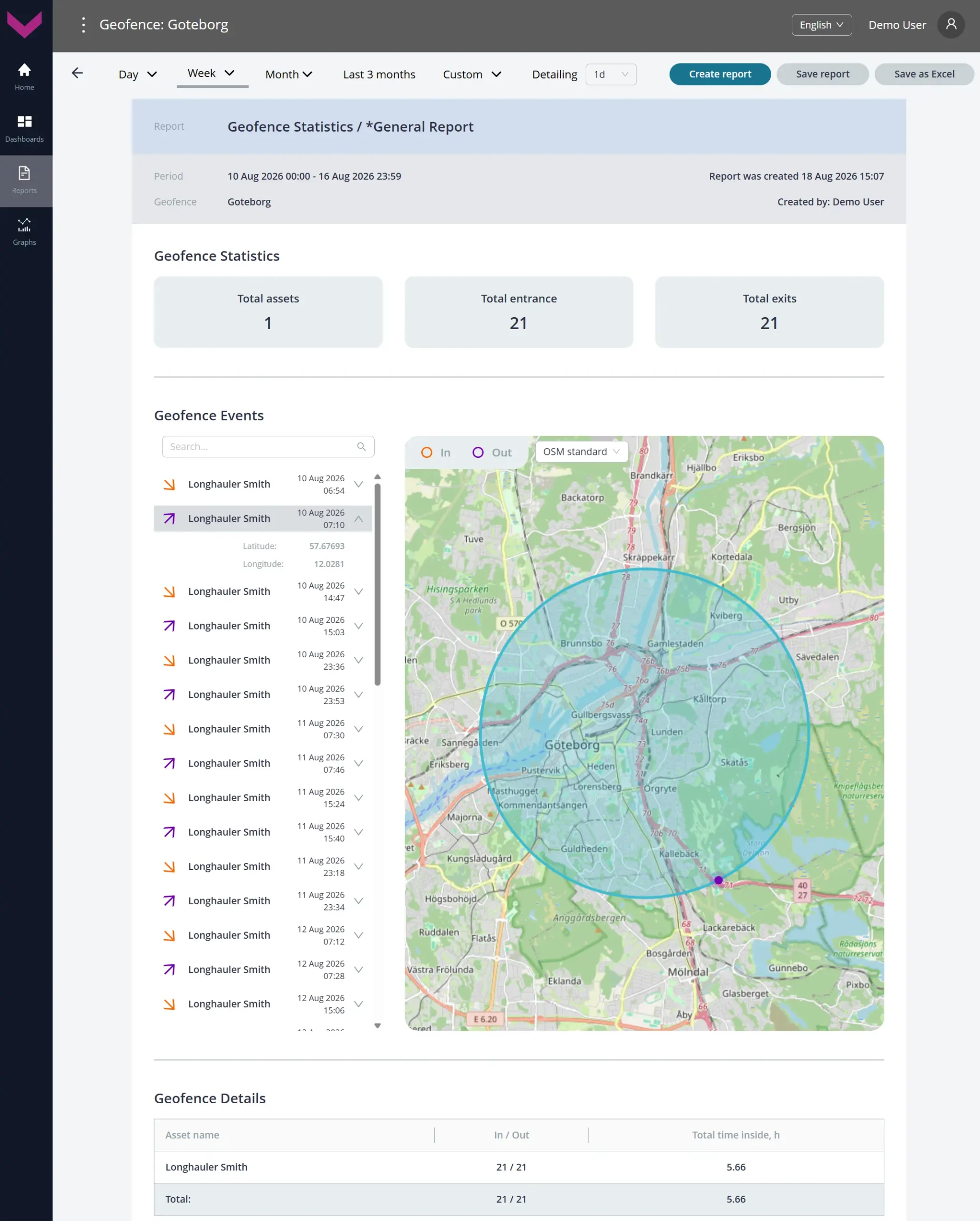
b) Analytical report *General Report for a one-week period
Figure 14 — Examples of data display for Task Geofence Statistics